¶ Overview
¶ Introduction
This document is designed to assist you in all of the functions readily available in the TFDi Design 717, and provides operating recommendations to help keep your flights as functional and stable as possible. Included are written descriptions and diagrams, where applicable, of onboard systems, flight controls, displays, and relevant indications.
A complete write-up of the 717’s Flight Management System (FMS) is included as a separate document.
¶ Abbreviations
| Abbreviation | Full Name |
|---|---|
| ACP | Audio Control Panel |
| ADIRU | Air Data Intertial Reference Unit |
| AFS | Auto Flight System |
| AND | Airplane Nose Down |
| ANU | Airplane Nose Up |
| ATS | Autothrottle System |
| CAWS | Central Aural Warning System |
| CONSEQ | Consequence |
| DIR INTC | Direct Intercept |
| DISAG | Disagree |
| DU | Display Unit |
| EAD | Engine and Alert Display |
| ECP | Electronic Control Panel |
| EEC | Electronic Engine Controller |
| EIS | Electronic Instrument System |
| EPCU | Electrical Power Control Unit |
| ET | Elapsed Time |
| FADEC | Full-Authority Digital Engine Controller |
| FCC | Flight Control Computer |
| FLEX TO | Flex Takeoff |
| FMA | Flight Mode Annunciator |
| FPA | Flight Path Angle |
| GCP | Glareshield Panel |
| GNSSU | Global Navigation System Sensor Unit |
| IDGS | Integrated Drive Generator System |
| IRU | Inertial Reference Unit |
| ISIS | Integrated Standby Instrument System |
| LSK | Line Select Key |
| MCDU | Multipurpose Control and Display Unit |
| MMO | Maximum Operating Mach |
| MMR | MultiMode Receiver |
| ND | Navigation Display |
| NL | Nose Left |
| NR | Nose Right |
| PBD | Place/Bearing/Distance |
| PCDU | Power Control and Distribution Unit |
| PFD | Primary Flight Display |
| PRSOV | Pneumatic System Pressure Regulator and Shutoff Valve |
| PSEU | Proximity Switch Electronics Unit |
| QFE | Field Elevation Pressure |
| QNH | Sea Level Pressure |
| SD | System Display |
| TA | Traffic Advisory |
| T/C | Top of Climb |
| T/D | Top of Descent |
| TR | Transformer Rectifier |
| VFE | Flap Extend Speed |
| VFR | Flap Retract Speed |
| VGE | Gear Extend Speed |
| VGR | Gear Retract Speed |
| VIA | Versatile Integrated Avionics |
| VMAX | Computer Calculated Maximum Operating Speed |
| VMIN | Computer Calculated Minimum Operating Speed |
| VREF | Reference Approach Speed |
| VS | Stall Speed |
| VSE | Slat Extend Speed |
| VSO | Clean Stall Speed |
| VSR | Slat Retract Speed |
| VSS | Stickshaker Speed |
| V3 | Final Climb Speed |
¶ Cockpit Layout
¶ Cockpit Areas

¶ Displays

¶ Aft Overhead
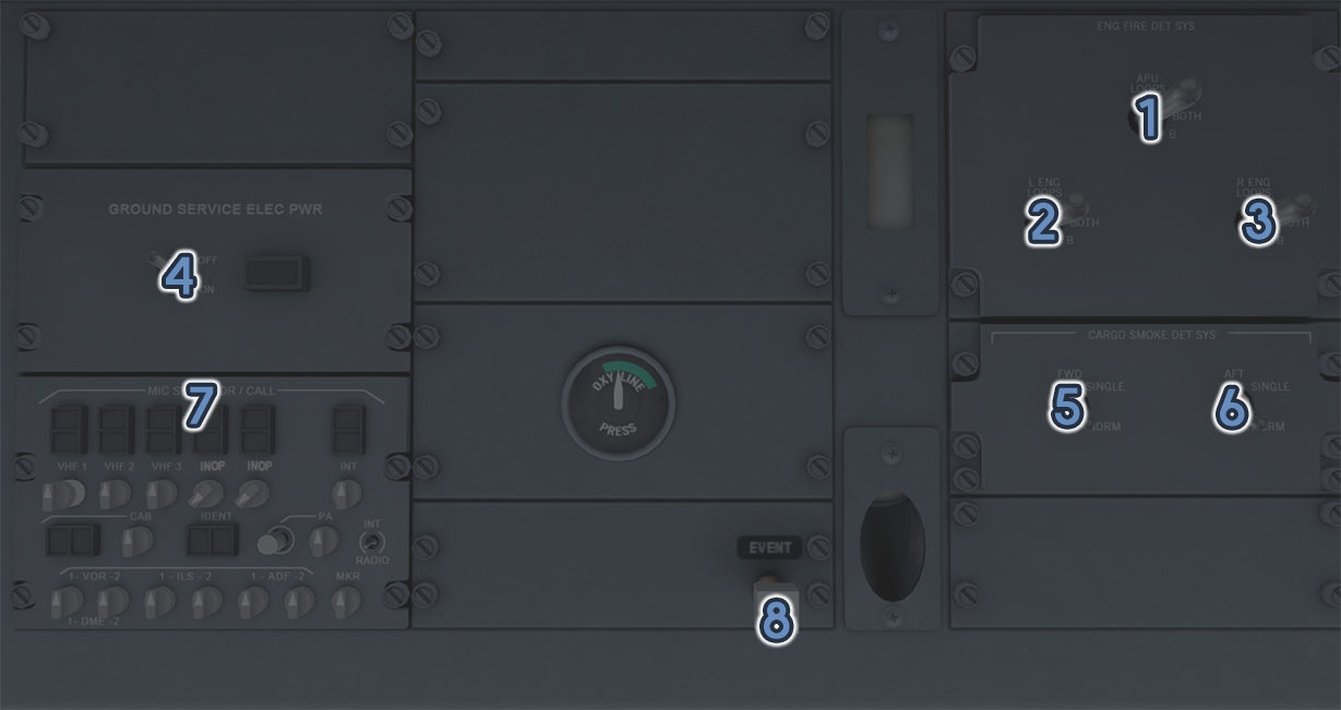
| ID | Name | Description |
|---|---|---|
| 1 | APU LOOPS | Connects the respective APU fire detector system(s) |
| 2 | LENG LOOPS | Connects the respective left engine fire detector system(s) |
| 3 | RENG LOOPS | Connects the respective right engine fire detector system(s) |
| 4 | GROUND POWER | Connects or disconnects external power to the AC ground service bus |
| 5 | CARGO SMOKE DET FWD | Selects single or dual (normal) forward cargo smoke detectors |
| 6 | CARGO SMOKE DET AFT | Selects single or dual (normal) aft cargo smoke detectors |
| 7 | OVERHEAD ACP | Controls audio output for the third audio system (not simulated) |
| 8 | EVENT SWITCH | Marks an event on the flight data recorder (not simulated) |
¶ Forward Overhead (Upper)
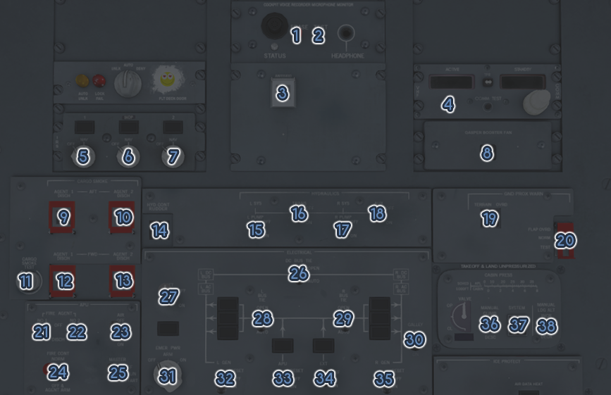
| ID | Name | Description |
|---|---|---|
| 1 | CVR ERASE | Erases the cockpit voice recorder memory if on ground with the parking brake set |
| 2 | CVR TEST | When held, tests the cockpit voice recorder and illuminates the STATUS light |
| 3 | ANTISKID | Activates/deactivates the antiskid system |
| 4 | VHF3 CONTROL PANEL | Provides controls for tuning, transfer, and testing of the VFH3 radio (not simulated) |
| 5 | IRS 1 | Turns ARIDU 1 on or off and if recycled within 5 seconds, initiates a fast realignment |
| 6 | IRS AUX | Turns the auxiliary ARIDU on or off and if recycled within 5 seconds, initiates a fast realignment (not simulated) |
| 7 | IRS 2 | Turns ARIDU 2 on or off and if recycled within 5 seconds, initiates a fast realignment |
| 8 | GASPER BOOSTER FAN | Turns gasper booster on or off to provide additional ventilation regardless of air conditioning packs |
| 9 | CARGO AFT FIRE AGENT 1 | Discharges cargo fire extinguishing agent 1 to the aft cargo area |
| 10 | CARGO AFT FIRE AGENT 2 | Discharges cargo fire extinguishing agent 2 to the aft cargo area |
| 11 | CARGO SMOKE TEST | When held, initiates a test of the cargo smoke detection system |
| 12 | CARGO FWD FIRE AGENT 1 | Discharges cargo fire extinguishing agent 1 to the forward cargo area |
| 13 | CARGO FWD FIRE AGENT 2 | Discharges cargo fire extinguishing agent 2 to the forward cargo area |
| 14 | HYD CONT RUDDER | Selects manual (airflow directed) rudder instead of hydraulic control |
| 15 | LEFT HYD PUMP | Turns the left engine-driven hydraulic pump on or off |
| 16 | HYD TRANS | Opens the valves on both sides of the hydraulic power transfer unit (PTU) to allow pressure transfer |
| 17 | RIGHT HYD PUMP | Turns the right engine-driven hydraulic pump on or off |
| 18 | AUX HYD PUMP | Turns the electric hydraulic pump on or off |
| 19 | EGPWS TERRAIN OVRD | Disables advanced EGPWS modes (simulation limited) |
| 20 | GPWS MODE | Respectively disables FLAP warning, enables normal operation, or initiates a partial test if not held or a full test if held |
| 21 | APU FIRE AGENT 1 | Discharges fire extinguishing agent 1 to the APU |
| 22 | APU FIRE AGENT 2 | Discharges fire extinguishing agent 2 to the APU |
| 23 | APU AIR | Enables or disables APU air |
| 24 | APU FIRE CONT | If set to OFF & AGENT ARM, shuts down APU immediately and arms the fire extinguishers |
| 25 | APU MASTER | In the off position, shuts the APU down and closes the inlet door, in the run position, allows APU run and opens the inlet door, or in the start position, starts the APU |
| 26 | DC BUS TIE | Sets automatic control of the DC bus ties |
| 27 | BATTERY | Connects or disconnects battery from the DC transfer bus |
| 28 | L BUS TIE | Sets automatic control of the left AC bus tie |
| 29 | R BUS TIE | Sets automatic control of the right AC bus tie |
| 30 | GALLEY PWR | Controls galley power |
| 31 | EMERGENCY PWR | Respectively turns off and resets the emergency power system, arms the system, or commands the emergency power system on |
| 32 | L ENG GEN | Connects the left engine IDGS to the electrical system |
| 33 | APU GEN | Connects the APU generator to the electrical system |
| 34 | EXT PWR | Connects external power to the electrical system |
| 35 | R ENG GEN | Connects the right engine IDGS to the electrical system |
| 36 | MAN PRESS | Progressively opens or closes the outflow valve |
| 37 | CABIN PRESS SYS | Toggles between manual and automatic cabin pressurization control |
| 38 | MAN LDG ALT | Increases or decreases landing altitude |
¶ Forward Overhead (Lower)
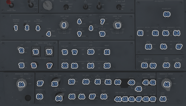
| ID | Name | Description |
|---|---|---|
| 1 | AVIONICS COOLING | If in air, OVRD opens the venturi valve and turns the radio rack fans off – inhibited on ground |
| 2 | RAM AIR | Controls the ram air valve position |
| 3 | PACK SHUTDOWN | In OVRD, disables automatic pack shutdown in most cases |
| 4 | FLOW | Controls air conditioning pack flow rate |
| 5 | CKPT TEMP | If in the auto range, sets the desired cockpit temperature for the air conditioning system – in the manual position, momentary turns control the cockpit temperature valve directly |
| 6 | L PACK | Respectively commands the left pack off or allows automatic control |
| 7 | R PACK | Respectively commands the right pack off or allows automatic control |
| 8 | ISOL | Respectively isolates the left and right pneumatic system, opens the valve fully, or allows automatic control of the valve |
| 9 | L BLEED | Respectively closes or allows automatic control of the left PRSOV |
| 10 | R BLEED | Respectively closes or allows automatic control of the right PRSOV |
| 11 | CABIN TEMP | If in the auto range, sets the desired cabin temperature for the air conditioning system – in the manual position, momentary turns control the cabin temperature valve directly |
| 12 | IGNITION | Respectively selects automatic control of the igniter power or powers the igniter continuously |
| 13 | LENG FADEC | Toggles between standard EPR control or manual N1 control of the left engine |
| 14 | RENG FADEC | Toggles between standard EPR control or manual N1 control of the right engine |
| 15 | START PUMP | Turns the DC start fuel pump on or off |
| 16 | L ENG START | Begins left engine cranking |
| 17 | R ENG START | Begins right engine cranking |
| 18 | FUEL QTY SELECT | Selects the A or B channel fuel quantity gaging system |
| 19 | L AFT PUMP | Turns the left aft fuel booster pump on or off |
| 20 | CTR AFT PUMP | Turns the center aft fuel booster pump on or off |
| 21 | R AFT PUMP | Turns the right aft fuel booster pump on or off |
| 22 | FUEL QTY TEST | When held, initiates a fuel system test display |
| 23 | L FWD PUMP | Turns the left forward fuel booster pump on or off |
| 24 | CTR FWD PUMP | Turns the center forward fuel booster pump on or off |
| 25 | R FWD PUMP | Turns the right forward fuel booster pump on or off |
| 26 | LEFT WINDSHIELD WIPER | Respectively returns the left wiper to its parked position, turns it off, sets it to slow, or fast movement |
| 27 | DOME | Controls cockpit dome lighting |
| 28 | OVHD LIGHTING | The rheostat (larger knob) controls overhead integral (back) lighting - the upper knob controls the overhead flood light |
| 29 | EMERGENCY LIGHTS | Respectively disables and turns off emergency lighting, arms it for use in the event of power loss, or turns it on |
| 30 | CIRCUIT BREAKER LIGHTS | Controls the circuit breaker light |
| 31 | NO SMOKING SIGN | Respectively enables automatic control of the cabin NO SMOKING light on, turns it off, or turns it on |
| 32 | SEAT BELT SIGN | Respectively enables automatic control of the cabin SEATBELT light on, turns it off, or turns it on |
| 33 | THUNDERSTORM LIGHTS | Controls the thunderstorm (full brightness) override of the cockpit flood lighting |
| 34 | INSTRUMENT AND PEDESTAL LIGHTING | The rheostat (larger knob) controls instrument and pedestal integral (back) lighting - the upper knob controls the instrument and pedestal flood light |
| 35 | LEFT LANDING LIGHT | Respectively retracts the left landing light, extends it with the lamp off, or extends it and illuminates the lamp |
| 36 | RIGHT LANDING LIGHT | Respectively retracts the right landing light, extends it with the lamp off, or extends it and illuminates the lamp |
| 37 | NOSE LIGHT | Respectively extinguishes the nose gear lamp, illuminates it to the taxi brightness, or illuminates it to the landing brightness |
| 38 | WING/NACELLE LIGHT | Respectively extinguishes the wing leading edge and engine nacelle light, illuminates both side’s lights, or illuminates the right side’s lights |
| 39 | CABIN PA SYSTEM | While held, connects either a headset or handset to the public address (PA) system |
| 40 | FLIGHT ATTENDANT CALL | Sounds the flight attendant chime and calls the cabin |
| 41 | MECHANIC CALL | Sounds the ground call horn and calls the ground |
| 42 | MAINTENCE INTERPHONE | Activates service interphone jacks throughout the aircraft |
| 43 | CALL RESET | Extinguishes the ATTND CALL and MECH CALL annunciators |
| 44 | LEFT GROUND FLOOD LIGHT | Controls the left ground flood light on the nose |
| 45 | RIGHT GROUND FLOOD LIGHT | Controls the right ground flood light on the nose |
| 46 | NAVIGATION LIGHT | Controls the position and navigation lights |
| 47 | LOGO LIGHT | Controls the logo light |
| 48 | BEACON LIGHT | Controls the beacon light |
| 49 | HIGH INTESITY LIGHT | Controls the strobe light |
| 50 | AIR DATA HEAT | Controls the heaters for pitots, rudder limiter, stall probes, static ports, and RAT probes |
| 51 | WING ICE PROTECTION | Controls the wing anti-ice |
| 52 | TAIL ICE PROTECTION | Controls the horizontal stabilizer anti-ice |
| 53 | WINDSHIELD ANTI-FOG | Controls the windshield, clearview, and overhead window anti-fog |
| 54 | WINDSHIELD ANTI-ICE | Controls windshield anti-ice |
| 55 | WING ICE DETECTION | Respectively resets the system and clears WING ICE DETECTED from the EAD or tests the wing ice detection system – switch rests in the neutral position |
| 56 | L ENG ICE PROTECTION | Controls left engine anti-ice heat |
| 57 | R ENG ICE PROTECTION | Controls right engine anti-ice heat |
| 58 | ANNUNCIATOR LIGHT DIM | When pulled, dims annunciator lights |
| 59 | ANNUNCIATOR LIGHT TEST | While held, initiates a test of annunciators and displays |
| 60 | FUEL USED RESET | Resets the current FUEL USED data |
| 61 | ENG EXCEEDENCE RESET | Resets and clears the ENG EXCEEDENCE data from the EAD |
| 62 | RIGHT WINDSHIELD WIPER | Respectively returns the right wiper to its parked position, turns it off, sets it to slow, or fast movement |
| 63 | STANDBY COMPASS LIGHT | Controls the standby compass light (not simulated) |
¶ Left Cockpit Wall
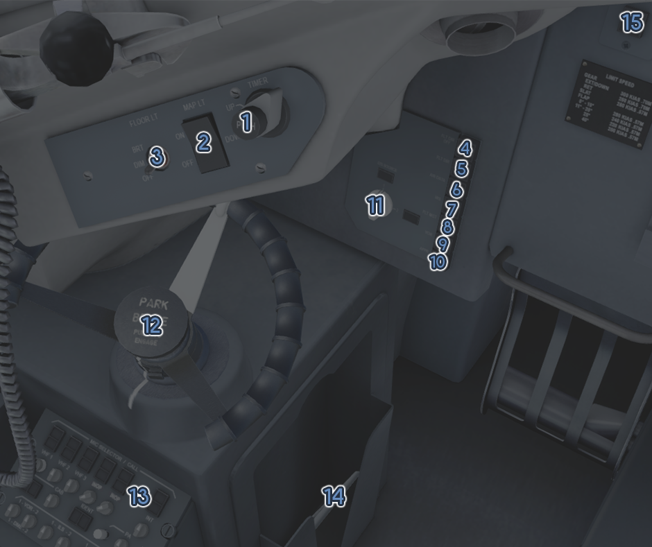
| ID | Name | Description |
|---|---|---|
| 1 | CAP TIMER | For EIS source 1, if starting from flight time display, a press selects and starts a manual timer, a second press stops the manual timer, and a third press selects flight time display |
| 2 | CAP MAP LIGHT | Controls the captain’s downward facing map light |
| 3 | CAP FLOOR LIGHT | Controls the captain’s floor light |
| 4 | CAP FLT DIR OFF | Disables the flight director for EIS source 1 |
| 5 | CAP FLT DIR | Selects offside flight director source for EIS source 1 |
| 6 | CAP AIR DATA | Selects offside air data source for EIS source 1 |
| 7 | CAP IRS | Selects offside IRS for EIS source 1 |
| 8 | CAP FLT MGT | Selects offside FMC for EIS source 1 |
| 9 | CAP VOR | Selects offside VOR source for EIS source 1 |
| 10 | CAP APPR | Selects the offside ILS source for EIS source 1 |
| 11 | CAP EIS SOURCE | Selects which EIS source is used on the left PFD and ND |
| 12 | PARK BRAKE | Controls the parking brake |
| 13 | CAP ACP | The rectangular buttons control the microphone destination, the knobs control the status and volume of the respective audio output (simulation limited) |
| 14 | CAP TABLET | This is the captain’s tablet (stowed in the picture) |
| 15 | CAP BELOW G/S | Inhibits the glide slope aural warning, if applicable |
¶ Right Cockpit Wall
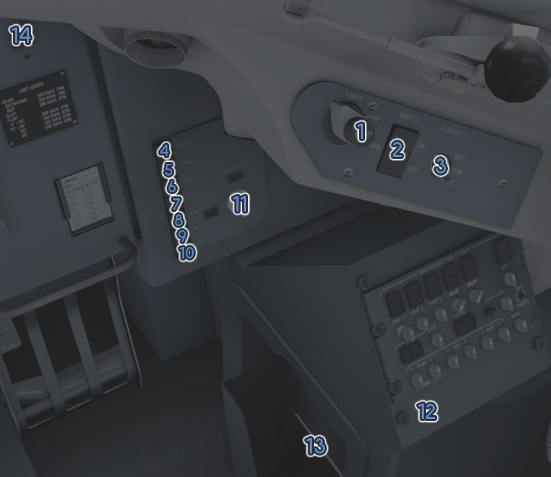
| ID | Name | Description |
|---|---|---|
| 1 | FO TIMER | For EIS source 2, if starting from flight time display, a press selects and starts a manual timer, a second press stops the manual timer, and a third press selects flight time display |
| 2 | FO MAP LIGHT | Controls the first officer’s downward facing map light |
| 3 | FO FLOOR LIGHT | Controls the first officer’s floor light |
| 4 | FO FLT DIR OFF | Disables the flight director for EIS source 2 |
| 5 | FO FLT DIR | Selects offside flight director source for EIS source 2 |
| 6 | FO AIR DATA | Selects offside air data source for EIS source 2 |
| 7 | FO IRS | Selects offside IRS for EIS source 2 |
| 8 | FO FLT MGT | Selects offside FMC for EIS source 2 |
| 9 | FO VOR | Selects offside VOR source for EIS source 12 |
| 10 | FO APPR | Selects the offside ILS source for EIS source 2 |
| 11 | FO EIS SOURCE | Selects which EIS source is used on the right PFD and ND |
| 12 | FO ACP | The rectangular buttons control the microphone destination, the knobs control the status and volume of the respective audio output (simulation limited) |
| 13 | FO TABLET | This is the first officer's tablet (stowed in the picture) |
| 14 | FO BELOW G/S | Inhibits the glide slope aural warning, if applicable |
¶ Glareshield and Instrument Panel
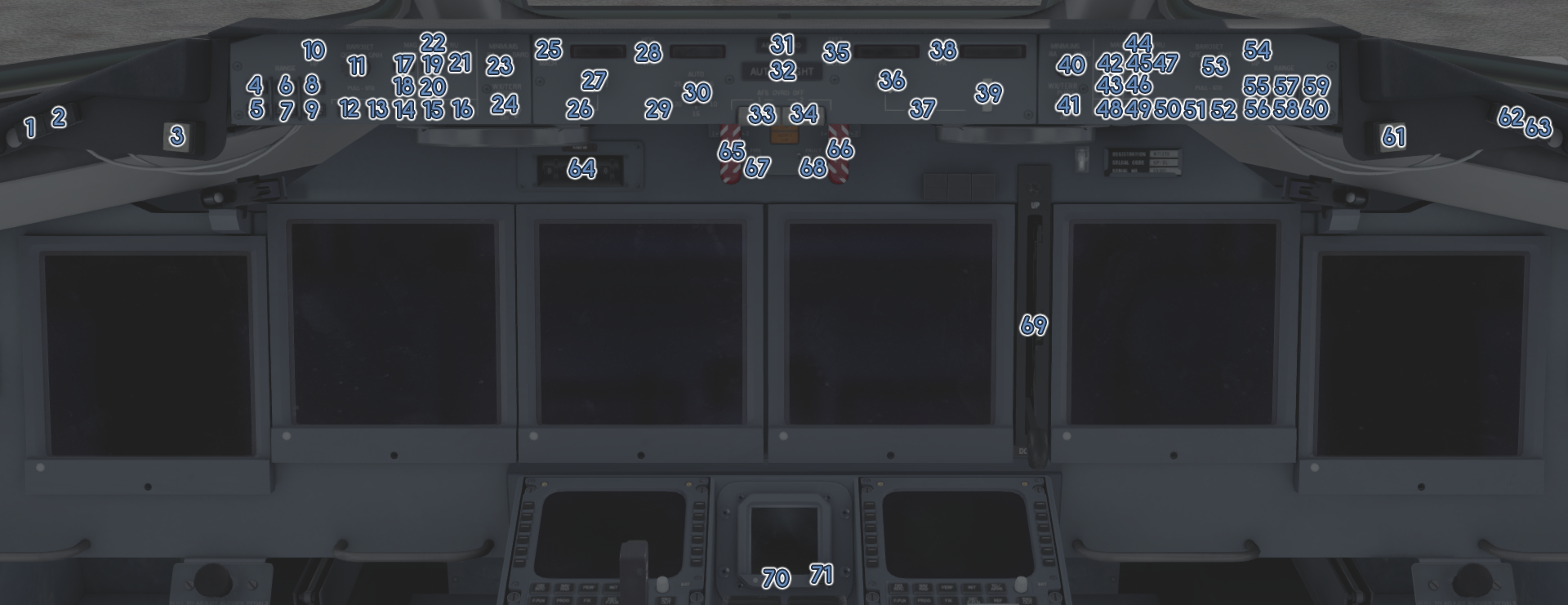
| ID | Name | Description |
|---|---|---|
| 1 | CAP MASTER WARNING | When pushed, extinguishes the light and silences the respective aural alert, as applicable |
| 2 | CAP MASTER WARNING | When pushed, extinguishes the master caution |
| 3 | CAP STICK PUSHER | Inhibits the stick pusher, if it is currently active |
| 4 | CAP VOR1 | Toggles VOR1 display for EIS source 1 |
| 5 | CAP ADF1 | Toggles ADF1 display for EIS source 1 |
| 6 | CAP INCREASE RANGE | Increases ND range for EIS source 1 |
| 7 | CAP DECREASE RANGE | Decreases ND range for EIS source 1 |
| 8 | CAP VOR2 | Toggles VOR2 display for EIS source 1 |
| 9 | CAP ADF2 | Toggles ADF2 display for EIS source 1 |
| 10 | CAP ALTIMETER MODE | Selects inches of mercury (IN) or hectopascals (HP) for the EIS source 1 altimeter |
| 11A | CAP ALTIMETER SET | The upper knob increments or decrements the EIS 1 source altimeter |
| 11B | CAP QFE/QNH SELECT | The lower knob selects between QFE and QNH altimeter mode for EIS source 1 |
| 12 | CAP TRAFFIC ON ND | Toggles between part-time or full-time traffic display on the ND for EIS source 1 |
| 13 | CAP DATA ON ND | Toggles waypoint data display on the ND for EIS source 1 |
| 14 | CAP WAYPOINTS ON ND | Toggles display of non-flight plan waypoints on the ND for EIS source 1 |
| 15 | CAP VORS/NDBS ON ND | Toggles display of non-flight plan VORs and NBDs on the ND for EIS source 1 |
| 16 | CAP AIRPORTS ON ND | Toggles display of non-flight plan airports on the ND for EIS source 1 |
| 17 | CAP MAP MODE | Selects MAP mode on the ND for EIS source 1 |
| 18 | CAP PLAN MODE | Selects PLAN mode on the ND for EIS source 1 |
| 19 | CAP VOR MODE | Selects VOR mode on the ND for EIS source 1 |
| 20 | CAP APPROACH MODE | Selects approach mode on the ND for EIS source 1 |
| 21 | CAP TCAS MODE | Selects TCAS mode on the ND for EIS source 1 |
| 22 | CAP HEADING MODE | Toggles between true and magnetic heading display on the ND for EIS source 1 |
| 23A | CAP MINIMUMS KNOB | The upper knob adjusts the minimums selection for EIS source 1 |
| 23B | CAP MINIMUMS MODE | The lower knob switches between barometric and radio altitude minimums for EIS source 1 |
| 24 | CAP WX/TERRAIN MODE | If pushed, switches between weather display and terrain display on the ND for EIS source 1 – if turned, adjusts the brightness of the weather/terrain overlay |
| 25 | AFS AIRSPEED MODE | Toggles between IAS and Mach display on the PFDs, AFS speed readout, and AFS speed selection |
| 26 | FMS SPEED | Selects FMS controlled speed targets for the AFS |
| 27 | AFS SPEED KNOB | Twisting the knob controls the preselected AFS speed, pushing it commands capture and hold of the current speed, pulling it commands hold of the preselected speed |
| 28 | AFS HEADING MODE | Toggles between heading and track display on the NDs, AFS heading readout, and AFS heading selection |
| 29 | NAV MODE | Arms or activates FMS guided AFS lateral control mode |
| 30A | AFS HEADING KNOB | Twisting the knob controls the preselected AFS heading, pushing it commands capture and hold of the current heading, pulling it commands hold of the preselected heading |
| 30B | AFS BANK LIMITER | Controls the bank limit for non-NAV AFS lateral control modes |
| 31 | AFS APPROACH/LANDING MODE | Arms or engages localizer and glide slope AFS lateral and vertical control modes as applicable |
| 32 | AUTOFLIGHT ENGAGE | Engages AFS and ATS or, and if autopilot is engaged, switches between EIS source 1 and 2 |
| 33 | AFS OVERRIDE 1 | If pulled, disconnects EIS source 1 AFS |
| 34 | AFS OVERRIDE 2 | If pulled, disconnects EIS source 2 AFS |
| 35 | ALTITUDE MODE | Toggles between feet and meters display on the PFDs, AFS altitude readout, and AFS altitude selection |
| 36 | AFS ALTITUDE KNOB | Twisting the knob controls the preselected AFS altitude, pushing it commands capture and hold of the current altitude, pulling it commands hold of the preselected altitude |
| 37 | AFS PROF MODE | Arms or activates FMS guided AFS vertical control mode |
| 38 | AFS VS MODE | Toggles FPA display on the PFDs and toggles between FPS and FPA on the AFS vertical rate readout and AFS vertical rate selection |
| 39 | AFS VS KNOB | If not in vertical rate (FPA or VS) vertical control mode, activates that mode, otherwise, adjusts target vertical rat |
| 40A | FO MINIMUMS KNOB | The upper knob adjusts the minimums selection for EIS source 2 |
| 40B | FO MINIMUMS MODE | The lower knob switches between barometric and radio altitude minimums for EIS source 2 |
| 41 | FO WX/TERRAIN MODE | If pushed, switches between weather display and terrain display on the ND for EIS source 2 – if turned, adjusts the brightness of the weather/terrain overlay |
| 42 | FO MAP MODE | Selects MAP mode on the ND for EIS source 2 |
| 43 | FO PLAN MODE | Selects PLAN mode on the ND for EIS source 2 |
| 44 | FO HEADING MODE | Toggles between true and magnetic heading display on the ND for EIS source 2 |
| 45 | FO VOR MODE | Selects VOR mode on the ND for EIS source 2 |
| 46 | FO APPROACH MODE | Selects approach mode on the ND for EIS source 2 |
| 47 | FO TCAS MODE | Selects TCAS mode on the ND for EIS source 2 |
| 48 | FO TRAFFIC ON ND | Toggles between part-time or full-time traffic display on the ND for EIS source 2 |
| 49 | FO DATA ON ND | Toggles waypoint data display on the ND for EIS source 2 |
| 50 | FO WAYPOINTS ON ND | Toggles display of non-flight plan waypoints on the ND for EIS source 2 |
| 51 | FO VORS/NDBS ON ND | Toggles display of non-flight plan VORs and NBDs on the ND for EIS source 2 |
| 52 | FO AIRPORTS ON ND | Toggles display of non-flight plan airports on the ND for EIS source 2 |
| 53A | FO ALTIMETER SET | The upper knob increments or decrements the EIS 2 source altimeter |
| 53B | FO QFE/QNH SELECT | The lower knob selects between QFE and QNH altimeter mode for EIS source 2 |
| 54 | FO ALTIMETER MODE | Selects inches of mercury (IN) or hectopascals (HP) for the EIS source 2 altimeter |
| 55 | FO VOR1 | Toggles VOR1 display for EIS source 2 |
| 56 | FO ADF1 | Toggles ADF1 display for EIS source 2 |
| 57 | FO INCREASE RANGE | Increases ND range for EIS source 2 |
| 58 | FO DECREASE RANGE | Decreases ND range for EIS source 2 |
| 59 | FO VOR2 | Toggles VOR2 display for EIS source 2 |
| 60 | FO ADF2 | Toggles ADF2 display for EIS source 2 |
| 61 | FO STICK PUSHER | Inhibits the stick pusher, if it is currently active |
| 62 | FO MASTER CAUTION | When pushed, extinguishes the light and silences the respective aural alert, as applicable |
| 63 | FO MASTER WARNING | When pushed, extinguishes the master caution |
| 64 | FLIGHT NUMBER SELECTOR | The four knobs can be rotated to display the current flight number to assist the crew |
| 65 | LEFT FIRE HANDLE | When pulled, shuts off fuel, hydraulic, electrical, and pneumatic systems for the left engine and arms the fire extinguishers – when turned left or right, discharges fire extinguishing agent 1 or 2 to the left engine, respectively |
| 66 | RIGHT FIRE HANDLE | When pulled, shuts off fuel, hydraulic, electrical, and pneumatic systems for the right engine and arms the fire extinguishers – when turned left or right, discharges fire extinguishing agent 1 or 2 to the right engine, respectively |
| 67 | FIRE TEST | When held, initiates a test of the fire system – when recycled before being held, the WING OVERHEAT warning tone may sound during the test |
| 68 | FIRE FAULT TEST | When held, initiates a fault test of the fire detection system |
| 69 | LANDING GEAR | Controls the position of the landing gear |
| 70 | ISIS ALIGN | Resets the ISIS attitude |
| 71 | ISIS ALTIMETER | Controls the altimeter setting of the ISIS |
¶ Pedestal
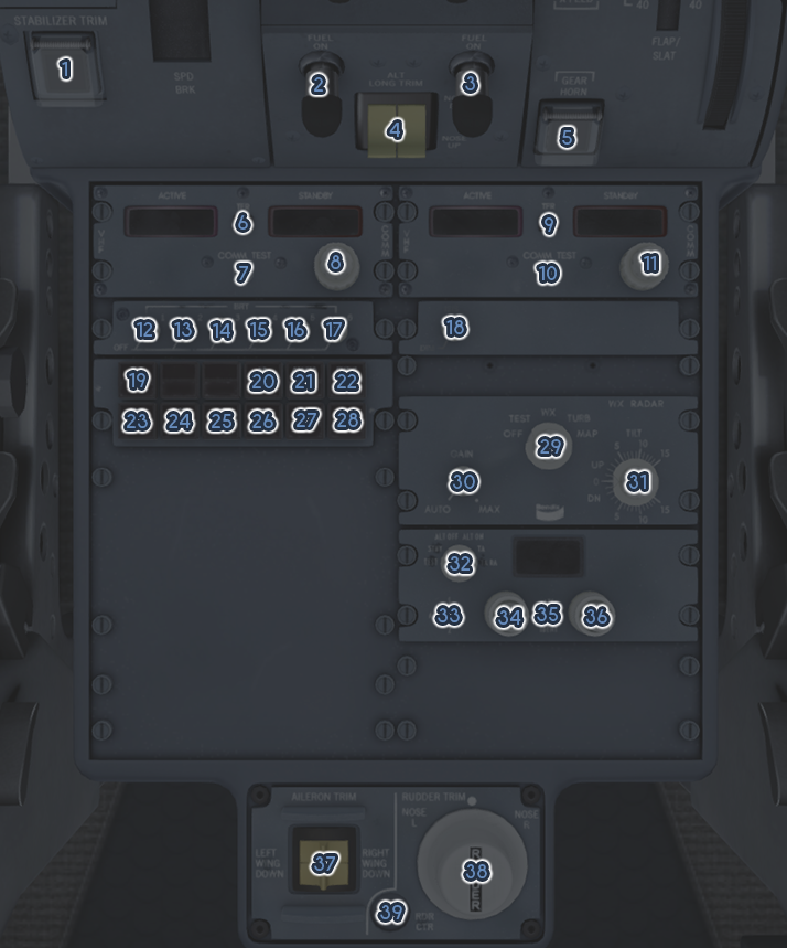
| ID | Name | Description |
|---|---|---|
| 1 | STAB TRIM INHIBIT | Toggles the primary stabilizer movement brake |
| 2 | L ENG FUEL VALVE | Controls the fuel valve position for the left engine |
| 3 | R ENG FUEL VALVE | Controls the fuel valve position for the right engine |
| 4 | ALT LONG TRIM | Controls trim via alternate movement of the horizontal stabilizer |
| 5 | GEAR HORN INHIBIT | Silences landing gear warning when possible |
| 6 | CAP VHF TRANSFER | Switches the VHF1 standby and active frequency |
| 7 | CAP COMM TEST | When held, temporarily disables VHF1 squelch (simulation limited) |
| 8 | CAP VHF TUNER | Controls the VFH1 standby frequency |
| 9 | FO VHF TRANSFER | Switches the VHF2 standby and active frequency |
| 10 | FO COMM TEST | When held, temporarily disables VHF2 squelch (simulation limited) |
| 11 | FO VHF TUNER | Controls the VFH2 standby frequency |
| 12 | CAP PFD BRIGHTNESS | Controls the brightness of DU 1 |
| 13 | CAP ND BRIGHTNESS | Controls the brightness of DU 2 |
| 14 | EAD BRIGHTNESS | Controls the brightness of DU 3 |
| 15 | SD BRIGHTNESS | Controls the brightness of DU 4 |
| 16 | FO ND BRIGHTNESS | Controls the brightness of DU 5 |
| 17 | FO PFD BRIGHTNESS | Controls the brightness of DU 6 |
| 18 | ISIS BRIGHTNESS | Controls the brightness of the ISIS |
| 19 | ENG SD CUE | Displays the engine synoptic page on the SD |
| 20 | ND SD CUE | Displays an ND on the SD |
| 21 | CONSEQ SD CUE | Displays the consequences page on the SD |
| 22 | STATUS SD CUE | Displays the status page on the SD |
| 23 | HYD SD CUE | Displays the hydraulic synoptic page on the SD |
| 24 | ELEC SD CUE | Displays the electrical synoptic page on the SD |
| 25 | AIR SD CUE | Displays the air synoptic page on the SD |
| 26 | FUEL SD CUE | Displays the fuel synoptic page on the SD |
| 27 | CONFIG SD CUE | Displays the configuration synoptic page on the SD |
| 28 | MISC SD CUE | Displays the miscellaneous page on the SD |
| 29 | WX MODE | Controls the mode of the weather radar |
| 30 | WX GAIN | Controls the gain of the weather radar |
| 31 | WX TILT | Controls the tilt angle of the weather radar |
| 32 | TCAS MODE | Controls the mode of the TCAS or, if moved into the TEST position, initiates a TCAS test |
| 33 | XPDR SELECT | Switches between transponder 1 and 2 |
| 34 | XPDR TUNER 1 | Adjusts the first two digits of the transponder code |
¶ Yoke
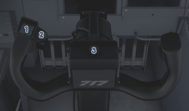
| ID | Name | Description |
|---|---|---|
| 1 | PRIMARY LONG TRIM | Controls trim via primary movement of the horizontal stabilizer |
| 2 | AP DISCONNECT | Disconnects the autopilot system |
| 3 | YOKE LIGHT | Controls the brightness of light located underneath the yoke |
¶ Throttle
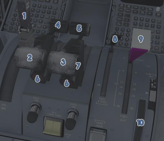
| ID | Name | Description |
|---|---|---|
| 1 | SPEEDBRAKE HANDLE | When pulled upward, arms the speedbrake for automatic deployment – when pulled downward, deploys the speedbrake |
| 2 | LEFT THROTTLE | Controls the commanded thrust from the left engine |
| 3 | RIGHT THROTTLE | Controls the commanded thrust from the right engine |
| 4 | LEFT REVERSER | Controls commanded reverse thrust from the left engine |
| 5 | RIGHT REVERSER | Controls commanded reverse thrust from the right engine |
| 6 | GO AROUND | During the approach phase, pressing either of these buttons activates the GO AROUND AFS control modes |
| 7 | AUTOTHROTTLE DISCONNECT | Disconnects the autothrottle system – pressing again clears the flashing ATS alert on the PFD |
| 8 | FUEL CROSSFEED | Opens or closes the fuel crossfeed valve |
| 9 | FLAP HANDLE | Selects the commanded slat and flap angle |
| 10 | TAKEOFF FLAP SELECTOR | Also known as dial-a-flap – selects a specific flap angle |
¶ EIS Alerts
¶ Overview
The EIS alerting system works with the MASTER WARNING, MASTER CAUTION, EAD, and SD to alert the pilot of various conditions in the aircraft.
¶ Alert Levels
- Level 0 - Minimal Attention Required: These appear only on the EAD in cyan, starting from the bottom of the right-most column.
- Level 1 - Attention Required: These appear in amber on the EAD and on the corresponding SD page.
- Level 2 - Immediate Attention Required: These appear in amber, surrounded by an amber box on the EAD and on the corresponding SD page. The MASTER CAUTION illuminates.
- Level 3 - Emergency: These appear in red, surrounded by a red box, and preceded by a triangle symbol on the EAD and on the corresponding SD page. The MASTER WARNING illuminates.
¶ Clearing Alerts
Most alerts appear initially on both on the EAD and the corresponding SD page, in reverse chronological order, grouped by level. A newly activated alert of level 1 or higher will cause the associated SD cue switch to illuminate.

Pressing the associated SD cue switch on the pedestal will acknowledge corresponding alerts, remove them from the EAD, and extinguish the SD cue light.
¶ Alert Behavior
If there are active alerts that have been removed from the EAD, the associated text for that will appear on the lower bottom right of the EAD as a reminder.
Some alerts display only on an SD page and skip the EAD. If an alert has appeared on an SD page but the SD cue has not been pressed, the reminder text will flash.
If an alert of level 2 or higher is activating the reminder, either flashing or static, the reminder text will be outlined in amber. A list of all active alerts of level 1 or higher can be found on the STATUS SD page.
¶ Consequences
Some alerts include consequences – additional information to remind the crew of limitations that may exist as a result of the condition that caused the alert. These will be displayed, if any exist for the alert, on the corresponding SD page and on the CONSEQ SD page.
¶ Takeoff and Landing Readiness
The bottom row of the middle row on the EAD will be convert to an essential checklist for takeoff or landing.

Before departure, the EAD can display the following items:
| Alert | Cause |
|---|---|
| STAB TRIM | Stabilizer trim does not agree with the FMS computed takeoff trim |
| RUDDER TRIM | Rudder trim is not centered |
| SLAT | The slats are not extended |
| FLAP | The flaps do not match the value entered into the MCDU |
| BRAKES | The parking brake is set |
| SPOILERS | The spoilers are not armed |
The displayed item will convert to red, except for SPOILERS, if the throttles are advanced and the condition isn’t satisfied.
During approach, the following items may be displayed on the EAD:
| Alert | Cause |
|---|---|
| LANDING GEAR | The landing gear is not extended |
| FLAP | The flaps are not in landing range |
| SPOILERS | The spoilers are not armed |
During departure or approach, once all conditions have been satisfied, a green box will be displayed.

¶ Alert List
Below is a list of all possible EIS alerts, their level, associated system or SD page, and an explanation of the alert. The ALERT column has been stylized to represent the appearance of the alert on the EAD and SD as closely as possible.
SYSTEM LEVEL ALERT CAUSE
| System | Level | Alert | Cause |
|---|---|---|---|
| AIR | 0 | AIR ISOL OPEN | The pneumatic isolation valve is open |
| AIR | 0 | CRG SMK TEST PASS | The cargo smoke system test has passed |
| AIR | 0 | PACKS HIGH FLOW | High pack flow has been selected |
| AIR | 1 | AIR SYS L NOT OFF | The left bleed air system has pressure while commanded off |
| AIR | 1 | AIR SYS L OFF | The left bleed air system is off and the isolation valve is closed |
| AIR | 1 | AIR SYS R NOT OFF | The right bleed air system has pressure while commanded off |
| AIR | 1 | AIR SYS R OFF | The right bleed air system is off and the isolation valve is closed |
| AIR | 1 | AVNCS COOL OVRD | The avionics cooling switch is in the override position |
| AIR | 1 | CAB PRES SYS MAN | The cabin pressurization system is in manual mode |
| AIR | 1 | CABIN RATE | The current cabin climb or descent rate exceeds limits |
| AIR | 1 | CABIN TEMP MANUAL | The cabin temperature knob is in the manual position |
| AIR | 1 | CARGO AGENT 1 LO | Cargo fire extinguishing agent 1 has been discharged |
| AIR | 1 | CARGO AGENT 2 LO | Cargo fire extinguishing agent 2 has been discharged |
| AIR | 1 | CKPT TEMP MANUAL | The cockpit temperature knob is in the manual position |
| AIR | 1 | CRG SMK AFT SGL | The aft cargo smoke detection system is in single mode |
| AIR | 1 | CRG SMK FWD SGL | The forward cargo smoke detection system is in single mode |
| AIR | 1 | LDG ALTITUDE MAN | Landing altitude is in manual selection mode |
| AIR | 1 | PACK L OFF | The left pack is commanded off |
| AIR | 1 | PACK OVRD | The pack shutdown switch is in the override position |
| AIR | 1 | PACK R OFF | The right pack is commanded off |
| AIR | 1 | SEL CAB PRES MAN | Both cabin pressure controllers have failed |
| AIR | 1 | START AIR PRES LO | Manifold pressure is insufficient for engine start |
| AIR | 2 | AIR SYS L PRES LO | The left air system is on but has low pressure |
| AIR | 2 | AIR SYS R PRES LO | The right air system is on but has low pressure |
| AIR | 2 | AVNCS AIR FLO OFF | When on ground, indicates the primary avionics fan has failed -in air, indicates both have failed with fan cooling selected |
| AIR | 2 | CABIN PRES HI | Cabin differential pressure exceeds limits |
| AIR | 3 | ►CABIN ALTITUDE | Cabin pressure altitude exceeds 10,000 feet |
| AIR | 3 | ►CARGO SMOKE AFT | Smoke has been detected by the aft cargo smoke detection system |
| AIR | 3 | ►CARGO SMOKE FWD | Smoke has been detected by the forward cargo smoke detection system |
| CONFIG | 0 | PARK BRAKE ON | The parking brake is on |
| CONFIG | 0 | SPEEDBRAKE | The speedbrake is extended |
| CONFIG | 1 | ANTISKID OFF | The antiskid braking system has been selected off |
| CONFIG | 1 | BRAKE PRES LO | One or more brake accumulator pressures are low |
| CONFIG | 1 | FCC 1 FAIL | FCC 1 has failed |
| CONFIG | 1 | FCC 2 FAIL | FCC 2 has failed |
| CONFIG | 1 | PSEU FAIL | The PSEU has failed |
| CONFIG | 1 | RUDDER PWR OFF | The rudder is in manual mode either due to loss of hydraulics or pilot selection |
| CONFIG | 1 | SPEEDBRAKE DISAG | The speedbrake is not deployed the amount the handle indicates it should be |
| CONFIG | 1 | SPEEDBRAKE/FLAP | The speedbrake is extended while the flaps are extended |
| CONFIG | 1 | SPOILER FAULT | The spoiler system has encountered a fault |
| CONFIG | 1 | SPOILER INBD FAIL | The inboard spoiler system has shut down due to a detected fault |
| CONFIG | 1 | SPOILER OTBD FAIL | The outboard spoiler system has shut down due to a detected fault |
| CONFIG | 1 | STAB TRIM OFF | The stabilizer trim is manually selected off |
| CONFIG | 1 | YAW DAMP FAIL | The yaw damper has been shut off by the FCC |
| CONFIG | 2 | BRAKE OVERHEAT | The brake temperature exceeds limits |
| CONFIG | 2 | FLAP DISAG | The flaps are not deployed the amount the handle indicates they should be |
| CONFIG | 2 | RUDDER LIM FAIL | Both primary and secondary rudder limiters have failed |
| CONFIG | 2 | SLAT DISAG | The slats are not deployed the amount the handle indicates they should be |
| ELEC | 0 | EMER POWER TEST | The emergency power test is in progress |
| ELEC | 0 | EXT POWER AVAIL | External power is available |
| ELEC | 0 | EXT POWER ON | External power is connected |
| ELEC | 1 | BATT CHARGING | The battery is currently charging |
| ELEC | 1 | BATT DISCHARGING | The battery is discharging abnormally |
| ELEC | 1 | BATT SWITCH OFF | The battery switch is in the off position |
| ELEC | 1 | BUS AC GS OFF | The AC ground service bus is not powered |
| ELEC | 1 | BUS AC L OFF | The left AC bus is not powered |
| ELEC | 1 | BUS AC R OFF | The right AC bus is not powered |
| ELEC | 1 | BUS DC L OFF | The left DC bus is not powered |
| ELEC | 1 | BUS DC R OFF | The right DC bus is not powered |
| ELEC | 1 | BUS TIE L OPEN | The left bus tie switch is in the open position |
| ELEC | 1 | BUS TIE R OPEN | The right bus tie switch is in the open position |
| ELEC | 1 | DC TIE SW OPEN | The DC bus tie switch is in the open position |
| ELEC | 1 | EMER PWR ON | Emergency power is on because of automatic activation or manual selection |
| ELEC | 1 | EMER PWR SW OFF | The emergency power switch is selected off |
| ELEC | 1 | GEN APU OFF | The APU generator is disconnected while the APU is running |
| ELEC | 1 | GEN L OFF | The left generator is selected off while the left IDGS is capable of providing power |
| ELEC | 1 | GEN R OFF | The right generator is selected off while the right IDGS is capable of providing power |
| ELEC | 2 | BUS AC EMER OFF | The emergency AC power bus is not powered |
| ELEC | 2 | BUS DC EMER OFF | The emergency DC power bus is not powered |
| ELEC | 2 | BUS DC XFER OFF | The DC transfer bus is not powered |
| ELEC | 2 | GEN ALL OFF | All generators are disconnected |
| ELEC | 2 | GEN L OFF | The left generator is off due to a fault |
| ELEC | 2 | GEN R OFF | The right generator is off due to a fault |
| ENG | 0 | APU AIR ON | APU air is selected on and providing air pressure |
| ENG | 0 | APU AIR/ELEC ON | The APU is providing power and air to the aircraft |
| ENG | 0 | APU ELEC ON | The APU is providing power to the aircraft |
| ENG | 0 | APU ON | The APU is running without a load |
| ENG | 0 | ENG IGN OVRD ON | The ignition switch is in the override position |
| ENG | 0 | ENGINE COOL | The engines have cooled enough for shutdown after landing |
| ENG | 1 | APU AUTO SHUTDOWN | The APU has detected a fault and shut down automatically |
| ENG | 1 | ENG L FADEC ALTN | The left FADEC is operating in alternate mode |
| ENG | 1 | ENG L START ABORT | An anomaly was detected and the autostart of the left engine was aborted |
| ENG | 1 | ENG R FADEC ALTN | The right FADEC is operating in alternate mode |
| ENG | 1 | ENG R START ABORT | An anomaly was detected and the autostart of the right engine was aborted |
| ENG | 1 | FIRE AGENT 1 LO | Fire extinguishing agent 1 has been discharged |
| ENG | 1 | FIRE AGENT 2 LO | Fire extinguishing agent 2 has been discharged |
| ENG | 1 | FIRE DET APU FAIL | Both APU fire detector systems have failed or a fire/overheat is detected in one of two active loops |
| ENG | 1 | FIRE DET L FAIL | Both left engine fire detector systems have failed or a fire/overheat is detected in one of two active systems |
| ENG | 1 | FIRE DET R FAIL | Both right engine fire detector systems have failed or a fire/overheat is detected in one of two active systems |
| ENG | 2 | SELECT FADEC ALTN | An engine has reverted to manual N1 control mode |
| ENG | 2 | START VLV L OPEN | The left start valve is open and the left engine N1 is higher than cutout speed (41%) |
| ENG | 2 | START VLV R OPEN | The right start valve is open and the right engine N1 is higher than cutout speed (41%) |
| ENG | 3 | ►APU FIRE | A fire has been detected in the APU |
| ENG | 3 | ►ENGINE L FIRE | A fire has been detected in the left engine |
| ENG | 3 | ►ENGINE R FIRE | A fire has been detected in the right engine |
| FUEL | 0 | ENG START PUMP ON | The DC start fuel pump is selected on |
| FUEL | 0 | FUEL SYS TEST | A fuel quantity system test is in progress |
| FUEL | 0 | FUEL XFEED ON | The fuel crossfeed valve is open |
| FUEL | 1 | CTR AFT PUMP OFF | The aft center fuel pump is off with usable fuel remaining |
| FUEL | 1 | CTR FWD PUMP OFF | The forward center fuel pump is off with usable fuel remaining |
| FUEL | 1 | ENG L FUEL PRES | The left engine has low fuel pressure |
| FUEL | 1 | ENG R FUEL PRES | The right engine has low fuel pressure |
| FUEL | 1 | FUEL LEVEL LO | Left or right fuel tank quantity has been below 2000 pounds for 2 minutes |
| FUEL | 1 | LAT FUEL UNBAL | The left and right fuel tank quantities differ by more than 1400 pounds |
| FUEL | 1 | SEL CTR PUMPS OFF | Center fuel tank quantity and pressure are low with the center fuel booster pumps on |
| FUEL | 1 | SEL CTR PUMPS ON | Center fuel booster pumps are off with usable fuel in the center tank |
| FUEL | 1 | TANK L PUMPS LO | The left fuel booster pump(s) have low pressure |
| FUEL | 1 | TANK L PUMPS OFF | Both forward and aft left fuel booster pumps are selected off with the left fuel switch on |
| FUEL | 1 | TANK R PUMPS LO | The right fuel booster pump(s) have low pressure |
| FUEL | 1 | TANK R PUMPS OFF | Both forward and aft right fuel booster pumps are selected off with the right fuel switch on |
| FUEL | 1 | TNK L AFT PMP LO | The left aft fuel booster pump has low pressure |
| FUEL | 1 | TNK L AFT PMP OFF | The left aft fuel booster pump is selected off with the left fuel switch on |
| FUEL | 1 | TNK L FWD PMP LO | The left forward fuel booster pump has low pressure |
| FUEL | 1 | TNK L FWD PMP OFF | The left forward fuel booster pump is selected off with the left fuel switch on |
| FUEL | 1 | TNK R AFT PMP LO | The right aft fuel booster pump has low pressure |
| FUEL | 1 | TNK R AFT PMP OFF | The right aft fuel booster pump is selected off with the right fuel switch on |
| FUEL | 1 | TNK R FWD PMP LO | The right forward fuel booster pump has low pressure |
| FUEL | 1 | TNK R FWD PMP OFF | The right forward fuel booster pump is selected off with the right fuel switch on |
| FUEL | 2 | BALST FUEL DISAG | A mismatch has been detected in the ballast fuel quantities |
| FUEL | 2 | CTR AFT PUMP LO | The center aft fuel booster pump is not producing pressure |
| FUEL | 2 | CTR FWD PUMP LO | The center forward fuel booster pump is not producing pressure |
| FUEL | 2 | FUEL OFF SCHEDULE | Either the left or right fuel tank has low fuel while the other has usable fuel |
| FUEL | 2 | FUEL QTY FAULT | There was a loss of fuel quantity gaging in one or more tanks |
| FUEL | 2 | FUEL QTY SYS FAIL | There was a complete loss of fuel quantity gaging on one channel |
| HYD | 1 | HYD AUX PUMP FAIL | The auxiliary hydraulic pump is selected on but not producing pressure |
| HYD | 1 | HYD AUX PUMP OFF | The auxiliary hydraulic pump is selected off with the slats extended and at least one engine on |
| HYD | 1 | HYD L OFF | The left engine-driven pump, hydraulic PTU, and auxiliary hydraulic pump are selected off |
| HYD | 1 | HYD PUMP L OFF | The left engine-driven pump is selected off |
| HYD | 1 | HYD PUMP R OFF | The right engine-driven pump is selected off |
| HYD | 1 | HYD R OFF | The right engine-driven pump, hydraulic PTU, and auxiliary hydraulic pump are selected off |
| HYD | 1 | HYD TRANS DISAG | The state of the hydraulic PTU does not match its commanded state |
| HYD | 1 | HYD TRANS OFF | The hydraulic PTU is selected off with the slats extended and at least one engine on |
| HYD | 2 | HYD L PRES LO | Left side hydraulic pressure is low |
| HYD | 2 | HYD R PRES LO | Right side hydraulic pressure is low |
| MAINT | 1 | CPC 1 FAULT | Cabin pressure controller 1 has failed |
| MAINT | 1 | CPC 2 FAULT | Cabin pressure controller 2 has failed |
| MAINT | 1 | DME 1 FAIL | DME receiver 1 has failed |
| MAINT | 1 | DME 2 FAIL | DME receiver 2 has failed |
| MAINT | 1 | FIRE APU A FAULT | APU fire detector system A has detected a fault |
| MAINT | 1 | FIRE APU B FAULT | APU fire detector system B has detected a fault |
| MAINT | 1 | FIRE L-A FAULT | Left engine fire detector system A has detected a fault |
| MAINT | 1 | FIRE L-B FAULT | Left engine fire detector system B has detected a fault |
| MAINT | 1 | FIRE R-A FAULT | Right engine fire detector system A has detected a fault |
| MAINT | 1 | FIRE R-B FAULT | Right engine fire detector system A has detected a fault |
| MAINT | 1 | GPS 2 FAULT | The GPS function of MMR 2 has failed |
| MAINT | 1 | ILS 2 FAIL | The ILS function of MMR 2 has failed |
| MAINT | 1 | PSEU FAULT | The PSEU has encountered an internal fault or failure |
| MAINT | 1 | STALL WARN FAULT | Two channels of stall warning or one channel of stick pusher have been lost |
| MAINT | 1 | STATIC L HEAT | The left static plate heater has failed |
| MAINT | 1 | STATIC R HEAT | The right static plate heater has failed |
| MAINT | 1 | VIA FAULT | The VIA has limited operations or the engine comparison monitor has failed |
| MAINT | 1 | VOR 2 FAIL | The VOR function of MMR 2 has failed |
| MISC | 0 | AIRFOIL A-ICE ON | Both wing and tail anti-ice are selected on with engine anti-ice is off |
| MISC | 0 | A-ICE ALL ON | All engine and airfoil anti-ice are selected on |
| MISC | 0 | CDU 1 MENU REQ | The left MCDU requires manual activation |
| MISC | 0 | CDU 2 MENU REQ | The right MCDU requires manual activation |
| MISC | 0 | ENG A-ICE ON | Both engine anti-ice switches are in the on position |
| MISC | 0 | ENG L A-ICE ON | The left engine anti-ice switch is in the on position |
| MISC | 0 | ENG R A-ICE ON | The right engine anti-ice switch is in the on position |
| MISC | 0 | GPWS FLAP OVRD | The GPWS mode switch is in the flap override position |
| MISC | 0 | IRS IN ALIGN | One or more IRUs are aligning |
| MISC | 0 | NO SMOKING | The cabin no smoking sign is on |
| MISC | 0 | SEAT BELTS | The cabin seat belt sign is on |
| MISC | 0 | TAIL A-ICE ON | Tail anti-ice is selected on and wing/engine anti-ice are selected off |
| MISC | 0 | TERRAIN OVRD | EGPWS terrain mode is off |
| MISC | 0 | WING A-ICE ON | Wing anti-ice is selected on and tail/engine anti-ice are selected off |
| MISC | 0 | WING ICE DET PASS | The upper wing surface ice detection system test has passed |
| MISC | 0 | WSHLD ANTI-FOG ON | The windshield anti-fog switch is in the on position |
| MISC | 1 | AIR DATA HEAT OFF | The air data heat pushbutton is in the off position |
| MISC | 1 | AOA HEAT L FAIL | The left AOA probe heater has failed and the air data heat pushbutton is in the on position |
| MISC | 1 | AOA HEAT R FAIL | The right AOA probe heater has failed and the air data heat pushbutton is in the on position |
| MISC | 1 | ATC XPDR 1 FAIL | Transponder 1 has failed |
| MISC | 1 | ATC XPDR 2 FAIL | Transponder 2 has failed |
| MISC | 1 | CABIN DOOR | The forward cabin door is open |
| MISC | 1 | CARGO DOOR AFT | The forward cargo door is open |
| MISC | 1 | CARGO DOOR FWD | The aft cargo door is open |
| MISC | 1 | DOOR OPEN | A door is open |
| MISC | 1 | DRAIN MAST HEAT | The drain mast heater has failed |
| MISC | 1 | EMER LTS DISARM | The emergency lights switch is in the OFF position |
| MISC | 1 | GALLEY DOOR | The galley door is open |
| MISC | 1 | GPWS FAIL | The GPWS has failed |
| MISC | 1 | GPWS FAULT | The GPWS has detected a fault |
| MISC | 1 | IRS 1 NO ALIGN | IRS 1 failed to complete alignment |
| MISC | 1 | IRS 2 NO ALIGN | IRS 2 failed to complete alignment |
| MISC | 1 | IRS 2 ON BATT | IRS 2 is being powered by the IRS battery |
| MISC | 1 | IRS BATT LO | The IRS battery is below 21 volts |
| MISC | 1 | IRS OFF | One or more ADIRUs have been selected off in flight |
| MISC | 1 | PITOT FO FAIL | The first officer’s probe heater has failed |
| MISC | 1 | PRED WSHEAR FAIL | The predictive windshear function is unavailable |
| MISC | 1 | RAT PROBE FAIL | The ram air probe heater has failed with the air data heat pushbutton in the on position |
| MISC | 1 | RUD PITOT FAIL | The rudder limiter pitot tube heater has failed failed with the air data heat pushbutton in the on position |
| MISC | 1 | STALL WARN FAIL | The stall warning system has failed |
| MISC | 1 | STICK PUSHER FAIL | The stick pusher has failed or is nearing an uncommanded push |
| MISC | 1 | TERRAIN FAIL | EGPWS terrain mode has failed |
| MISC | 1 | WSHEAR DET FAIL | Windshear detection is inoperative |
| MISC | 1 | WSHLD A-ICE OFF | Windshield anti-ice is selected off |
¶ Aural Alerts
¶ Overview
The aircraft is capable of producing various systems-related alerts in addition to standard GPWS alerts. The CAWS has a priority system, allowing it to play the most important or relevant alert first.
In the event of a repeating aural alert, after three cycles, the CAWS will automatically reduce the volume of that alert until it is cleared or another alert plays.
¶ Aural Alert List
Below is a list of all possible aural alerts and any additional tone or sound that accompanies them. They are ordered in relative priority. For a more detailed explanation of certain alerts, please see the relevant sections of this document.
| Tone | Alert | Cause |
|---|---|---|
| GO AROUND | The predictive windshear warning system has determined the pilot should initiate a go-around (not simulated) | |
| 2xWHOOP | PULL UP | Penetration of the inner excessive descent rate boundary |
| TERRAIN TERRAIN, PULL UP | Excessive terrain closure rate in landing configuration (not simulated) | |
| LONG HORN | CABIN ALTITUDE | Cabin pressure altitude has exceeded 10,000 feet |
| WINDSHEAR AHEAD | Close proximity windshear detected (not simulated) | |
| TERRAIN | Excessive terrain closure rate (not simulated) | |
| 4xKLAXON | STALL | AOA at or near the current stall AOA |
| BELL | FIRE RIGHT ENGINE | A fire has been detected in the right engine |
| BELL | FIRE LEFT ENGINE | A fire has been detected in the left engine |
| 3xTRITONE | Wing overheat detection | |
| 5xSHORT HORN | APU FIRE | A fire has been detected in the APU |
| 5xSHORT HORN | CARGO SMOKE | Smoke has been detected in the cargo area |
| CLACKER | OVERSPEED | VMO or MMO has been exceeded |
| CLACKER | SLAT OVERSPEED | Maximum slat operating speed has been exceeded with the slats extended |
| 5xALARM | AUTOPILOT | Autopilot has been disconnected – cleared by pressing the AP DISCONNECT button |
| MINIMUMS | Crossing the minimums altitude | |
| CAUTION, TERRAIN | Penetration of the of terrain look ahead envelope (not simulated) | |
| TOO LOW, TERRAIN | Unsafe terrain clearance | |
| 1000, 500, 400, 300, 200, 100, 50, 40, 30, 20, 10, 5 | Radio altitude callouts to assist during approach | |
| TOO LOW, GEAR | Unsafe terrain clearance with landing gear up | |
| TOO LOW, FLAPS | Unsafe terrain clearance with flaps up | |
| LONG HORN | SPEED BRAKE | The speedbrake is extended with the flaps extended |
| LONG HORN | LANDING GEAR | Landing gear retracted either when throttles retarded at less than 210 knots and below 1200 feet, or flaps are in landing range |
| SINK RATE | Excessive ground-proximate descent rate | |
| DON'T SINK | Altitude loss after takeoff | |
| GLIDE SLOPE | The aircraft has fallen significantly below the glide slope | |
| MONITOR RADAR DISPLAY | Proximate wind shear detected (not simulated) | |
| C-CHORD | ALTITUDE | Approaching selected altitude |
| LOW CHORD | STABILIZER MOTION | Stabilizer has moved over 1 unit continuously |
| APPROACHING MINUMUMS | Aircraft is 100 feet above the minimums altitude | |
| PLUS HUNDRED | Aircraft is 100 feet above the minimums altitude | |
| BANK ANGLE, BANK ANGLE | Excessive bank or roll | |
| CLIMB, CLIMB | TCAS is instructing a climb to resolve the traffic conflict | |
| CLIMB, CROSSING, CLIMB | TCAS is instructing a climb to resolve the traffic conflict – the conflicting aircraft will cross altitudes with you | |
| DESCEND, DESCEND | TCAS is instructing a descent to resolve the traffic conflict | |
| DESCEND, CROSSING, DESCEND | TCAS is instructing a descent to resolve the traffic conflict – the conflicting aircraft will cross altitudes with you | |
| ADJUST VERTICAL SPEED, ADJUST | TCAS is instructing a modification to the current vertical speed to resolve the traffic conflict | |
| MONITOR VERTICAL SPEED | TCAS is advising the pilot to monitor current vertical speed due to a conflicting aircraft | |
| MAINTAIN, CROSSING, MAINTAIN | TCAS is instructing maintaining vertical speed to resolve the traffic conflict – the conflicting aircraft will cross altitudes with you | |
| MAINTAIN VERTICAL SPEED, MAINTAIN | TCAS is instructing maintaining vertical speed to resolve the traffic conflict | |
| TRAFFIC, TRAFFIC | Traffic advisory | |
| CLEAR OF CONFLICT | Traffic conflict resolved | |
| TCAS TEST PASS | The TCAS self-test has passed | |
| TCAS TEST FAIL | The TCAS self-test has failed | |
| 2xHORN | STABILIZER | Both throttles advanced with stabilizer trim not within the green band |
| 2xHORN | RUDDER TRIM | Both throttles advanced with rudder trim not centered |
| 2xHORN | SLATS | Both throttles advanced with slats not extended |
| 2xHORN | FLAPS | Both throttles advanced with flaps not in the takeoff setting entered into the MCDU |
| 2xHORN | BRAKES | Both throttles advanced with the parking brake set |
| 2xHORN | SPOILERS | Both throttles advanced with the spoilers extended |
¶ Systems
¶ Air (Pneumatic) System
¶ Overview
The 717 has two identical air sub-systems capable of the following:
- Pressurization
- Air conditioning
- Anti-ice
- Engine start
- Potable water system pressurization
Air conditioning controls are on the forward overhead panel.
¶ Air Synoptic Display
The air SD page, accessible by pressing the AIR SD cue switch, displays the following:
- Air system flow
- Airflow duct and zone Temperature
- Valve positions
- Pressurization status
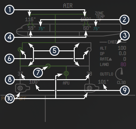
| ID | Name | Description |
|---|---|---|
| 1 | COCKPIT AND CABIN DUCT TEMPERATURE | Displays the temperature of the air in the corresponding duct |
| 2 | TARGET ZONE TEMPERATURE | In automatic control mode, this is the target temperature of the zone – in manual control mode, three dashes appear and the position of the temperature control valve is shown on the upper corner of the display |
| 3 | PRESSURIZATION STATUS | Displays: Cabin pressure altitude, differential pressure, cabin climb/descent rate, landing altitude, and the outflow valve position Landing Altitude: Magenta cabin altitude indicates it is FMS controlled – manual selection will be indicated and boxed in amber |
| 4 | COCKPIT AND CABIN ZONE TEMPERATURES | Displays the current temperature in the corresponding zone |
| 5 | AIR FLOW INDICATOR LINES | Green indicates air is flowing |
| 6 | PACK STATUS INDICATOR | Green Fan: Pack commanded on with air flow, White Circle: Pack commanded off with no air flow, Amber Fan: Pack commanded on with no air flow, Amber Circle: Pack commander off with no air flow |
| 7 | ISOLATION VALVE | White: Commanded close, Green: Commanded open with air flow, Amber: Disagrees with switch position |
| 8 | MANIFOLD PRESSURE | Indicates the manifold pressure – amber and boxed when outside of normal range |
| 9 | BLEED AIR TEMPERATURE | Temperature of the bleed air – amber and boxed when outside of normal range |
| 10 | AIR SOURCE STATUS INDICATORS | Shows current status of airflow sources – green valves indicate open and providing air flow, white circles indicate closed |
¶ Pneumatic Sub-Systems
- Isolation Valve: The isolation valve separates the left and right air systems. The aircraft will attempt to keep them isolated at all times. In the event of a loss of pressure to one side, the isolation valve, when controlled automatically, will open to pressurize the anti-ice systems. It must be manually opened for air conditioning and engine starter operation.
- Auto Pack Shutdown: In the event of an engine failure below 3000 feet AGL, both air conditioning packs will shut down to preserve thrust in the remaining engine. They can also be automatically shut off during departure by selecting PACKS OFF in the MCDU.
- Ram Air: Ram air can provide pressurization to the air system if standard bleed air is not available.
- Air Conditioning: The air conditioning system consists of separate cockpit and cabin conditioning and a gasper booster fan to provide additional ventilation. When operating the gasper booster fan, if the packs are not running, the ram air valve must be opened to allow air flow.
- Pressurization: The outflow valve controls cabin pressurization rate. When in automatic pressurization control mode, the system will open and close the valve as required. Standard maximum cabin differential pressure is 7.86 psi. At 19,000 feet, the system will maintain sea level pressure in the cabin. At 37,000 feet, it will maintain a pressure altitude of 8,000 feet in the cabin. If in manual mode, it is the pilot’s responsibility to monitor pressurization status and adjust as required. If the landing altitude is set manually, it will be reset to automatic mode upon the next entry of a flight plan.
- Cargo Heating/Pressurization: The forward cargo compartment is heated electrically to maintain reasonable temperatures. Living or temperature sensitive cargo must be transported forward of the cargo door. The cargo compartments are equalized with cabin pressure.
- Radio/Instrument Cooling:
Avionics and radio cooling is provided automatically on the ground. In the air, the avionics cooling switch can be used can be used to switch between fan and venturi airflow cooling. The displays are cooled by either a fan or pack airflow.
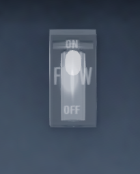
With both packs selected on, the fan will turn off – it is imperative for the pilot to ensure that there is airflow to the cooling via the airflow indicator on the instrument panel (pictured above) by ensuring that either one pack switch is off or the packs have air flow. The egg-shaped object will appear at the top of the tube when there is sufficient air flow.
¶ Auxiliary Power Unit (APU)
¶ Overview
The auxiliary power unit exists to provide electrical power and pneumatic pressure to the aircraft without the engines or as a supplement/backup to the standard supplies.
¶ APU Operation
The APU uses the battery to start. The start process is automated after the master switch is released to the run position. There is a delay before APU runup to allow for the inlet door to open.
The APU normally consumes fuel from the right main tank. A pump is required to start, but not run, the APU. The DC start pump or an appropriate AC pump is sufficient to start the APU.
Electrical power is available immediately after APU runup. APU air is available approximately 2 minutes after APU start, on the ground only.
During a normal shutdown, the APU will continue running for approximately 17 seconds to allow the electrical system to smoothly transfer power to other sources. If the APU shuts down because the APU FIRE CONT switch was moved to the OFF & AGENT ARM position, the delay is skipped.
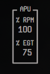
¶ APU Data
The APU EGT and RPM percent are displayed on the engine synoptic page.
¶ Electrical System
¶ Overview
The 717 is equipped with an automatic power control system. The majority of system operation is controlled by the EPCU and the PCDUs for each generator.
Each engine has an IDGS that provide independent power, both capable of powering the aircraft’s systems. The IDGS converts variable speed mechanical energy from the engines into constant, reliable electricity. The APU also provides sufficient power for the entire aircraft. An external power generator can be connected for quicker and more fuel-efficient operation.
¶ Emergency Power
The emergency power system, when armed, will automatically connect the DC battery to the emergency DC bus and emergency AC bus through the emergency TR. Not all aircraft systems will be available via emergency power, only those essential for flight.
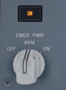
Once activated, the emergency power system must be reset by moving the switch to the off position before being moved back to arm, or it will remain active and continue to discharge the battery. When emergency power is active, or during a test, ON will illuminate on the annunciator near the switch.
¶ Power Distribution
The 717 distributes power automatically and will attempt to isolate the left and right AC and DC systems. With the bus tie switches in the auto position, if power is lost to any buses, the system will automatically open and close the appropriate relays to supply power from the offside system.
Power transfer occurs via a No Break Power Transfer (NBPT) to avoid disruptions in aircraft systems. This function is driven by the EPCU.
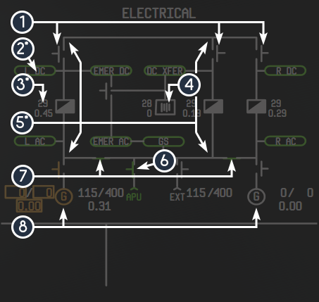
¶ Electrical Synoptic Display
The electrical synoptic display is accessible by pressing the ELEC SD cue switch.
Note: Elements that show more than once on the display (with different data) are marked with an asterisk.
| ID | Name | Description |
|---|---|---|
| 1 | DC BUS TIE RELAYS | These appear in white and separated when open and in green touching the flow lines |
| 2* | BUS INDICATORS | These appear as green ovals when powered and amber ovals with OFF displayed adjacent when not powered |
| 3* | TRANSFORMER RECTIFIERS | These indicate the current load and voltage on the corresponding TR |
| 4 | BATTERY | This appears in white if idling and charged, in green if charging, and in amber if discharging – voltage and load are shown adjacent |
| 5* | ELECTRICAL FLOW LINES | These indicate the current flow of electricity throughout the system |
| 6 | APU AND EXTERNAL GENERATOR STATUS | APU and external are shown as a white T if available and disconnected, or a green T if connected and producing power – frequency and voltage are shown adjacent for both, load is also shown for APU |
| 7 | AC BUS TIE RELAYS | These appear in white and separated when open and in green touching the flow lines |
| 8 | ENGINE GENERATOR STATUS | These display as a white G if disconnected, in amber if connected and producing insufficient power, or green if connected and producing sufficient power – frequency, voltage, and load are shown adjacent in white if normal or in amber and boxed if abnormal |
¶ Electrical Annunciators
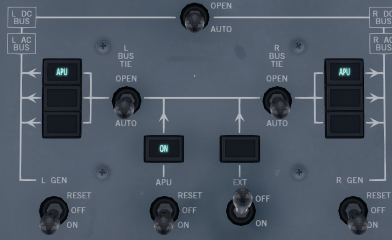
On the overhead panel, annunciators will display the source of power to the corresponding AC BUS, if it is not the standard, on-side source. In the image below, both left and right AC buses are being powered by the APU. Annunciators above the APU and external power switch will indicate their status.
¶ Engines
¶ Overview
The 717 is equipped with two high-bypass turbo fan engines capable of producing a maximum of 21,000 pounds of thrust each. These engines have a clamshell style thrust reverser. The engines are controlled via the EEC and FADEC.
¶ Throttle Levers and Reverse Thrust
The throttle levers can be moved to command a specific thrust from the FADEC. There is a gate at the end of the range of motion that the throttles can be forced through. In this position, they will command emergency thrust and exceed current limits. If left in this position, the FADEC will revert to manual N1 mode.
Pulling the reverse thrust levers up will unlock and engage the reversers.
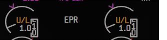
An amber “U/L” will appear inside the EPR dial when the reverser clamshells are unlocked, but not fully deployed or stowed.
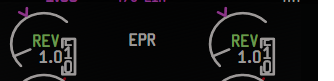
When the reverser clamshells have deployed fully, REV will appear in green inside the EPR dial.
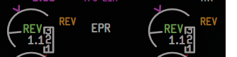
The reverser handles have a gate at the edge of their range of motion that when entered, will activate emergency reverse thrust. This will cause REV to appear in amber adjacent to the EPR dial until the ENG EXCEEDENCE RESET button is pressed. Emergency reverse can be harmful to the engine.
Reverse thrust is available only with the nose wheel on the ground. If an engine has failed, the EEC will allow the reverser on the failed engine to deploy for up to 60 seconds after landing to avoid differential drag.
¶ FADEC
The FADEC works by converting commanded thrust from the throttle levers to an appropriate amount of thrust from the engines.
In standard EPR control mode, the throttle position will correspond to a specific EPR between the calculated idle EPR and EPR limit at that moment. The FADEC will account for numerous aircraft and atmospheric conditions and adjust the engines to reach that EPR throughout the flight.
In manual N1 control mode, the FADEC will convert commanded thrust to a corresponding N1 percent.
¶ Exceedence
In the event that certain engine parameters, such as N1, TGT, or N2, exceed normal operational limits, the maximum reached value will be displayed in amber next to the corresponding indication on the EAD. These can be cleared via the ENG EXCEEDENCE RESET button on the overhead.
¶ Startup
The engines are capable of a full automatic start procedure, driven by the EEC. The engines require a minimum of 32 PSI in the manifold to start. Startup can be initiated by pulling the respective engine start knob.

In automatic startup mode, the EEC will monitor engine parameters and abort the start if any anomalies are detected. At approximately 22% N1, the EEC will power the igniter. This is indicated by a cyan lightning bolt inside the TGT dial.
If TGT is above 150°C, the EEC will motor the engine to allow it to cool sufficiently. At approximately 40% N1, the EEC will close the start valve.
In manual mode, it is the pilot’s responsibility to monitor engine parameters and introduce fuel at approximately 19% N1, as the igniter is continuously powered. After start, the ignition switch should be returned to the auto position.
¶ ENGINE AND ALERTS DISPLAY (EAD)
The EAD displays engine parameters and the EIS alerts.
Note: Elements that show more than once on the display (with different data) are marked with an asterisk.
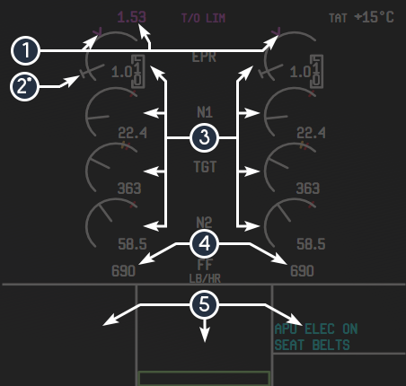
| ID | Name | Description |
|---|---|---|
| 1 | THRUST LIMIT INDICATOR | Indicates the current thrust limit – shown as a magenta V riding the EPR dial and the textual representation is written in magenta on the top of the EAD |
| 2* | COMMANDED EPR | This in an indication of the current commanded EPR |
| 3 | ENGINE PARAMETERS | The dials indicate the corresponding engine data – limits are shown as red lines through the dial |
| 4 | FUEL FLOW INDICATOR | Current engine fuel flow |
| 5 | EIS ALERT DISPLAY | Three columns that display EIS alerts and the takeoff and landing readiness checklists |
¶ Engine Synoptic Display
The engine synoptic display is accessible by pressing the ENG SD cue switch.
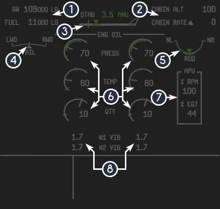
| ID | Name | Description |
|---|---|---|
| 1 | WEIGHT DISPLAYS | Displays gross weight and usable fuel weight |
| 2 | CABIN PRESSURIZATION STATUS | Displays current cabin pressure altitude and cabin climb or descent – if values are exceeded, values will be displayed and boxed in red or amber, respectively |
| 3 | STAB TRIM | Displays current horizontal stabilizer trim – green band indicates FMS calculated takeoff trim |
| 4 | AILERON TRIM | Displays current left/right aileron trim |
| 5 | RUDDER TRIM | Indicates current rudder trim – a green band is displayed to indicate center when on the ground |
| 6 | OIL DATA | Displays oil pressure, temperature, and quantity – a blue line appears on the quantity dial to indicate the initial level as measured upon engine start |
| 7 | APU STATUS | If APU is running, displays the RPM and EGT of the APU |
| 8 | ENGINE VIBRATION DATA | Displays current N1 and N2 vibration |
¶ Flight Controls
¶ Overview
The aircraft flight control system consists of various components. Each system is explained in more detail below. Certain controls are aerodynamically positioned, meaning that a control tab on the surface deflects when a movement is commanded, which in turn causes drag to push the control surface. This also means that the effectiveness of these controls is dependent on airflow.
¶ Ailerons
There are two tabs located on each aileron. Both tabs are pictured below, and are shown deflected upward (independently in each image).
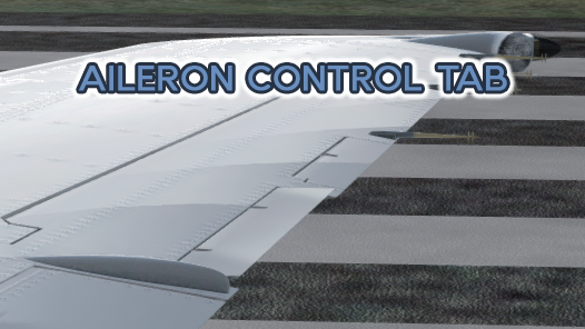

The ailerons are positioned aerodynamically by the aileron control tab, located on the control surface. The deflection of this tab causes the aileron itself to deflect. Because of this, the aileron control tab movement is inverted compared to the aileron itself.
The aileron trim is controlled by a tab next to the aileron control tab. This tab works similarly to the aileron control tab and deflects air to trim the aileron.
¶ Elevator
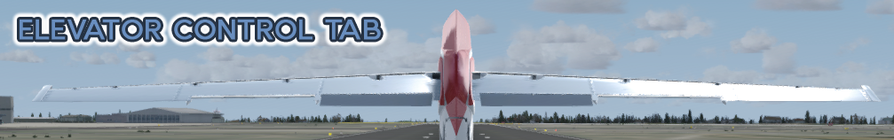
The elevator is controlled aerodynamically by the two elevator control tabs (pictured above, deflected downward). The elevator is hydraulically assisted when moving downward to allow the pilot, or stall prevention system, to move the elevator regardless of airflow.
A geared tab next to the control tab moves as the elevator itself moves to assist with positioning.
¶ Horizontal Stabilizer (Longitudinal) Trim

The stabilizer trim control (pictured above, fully trimmed upward) causes the elevator to rotate upward or downward to compensate for differences in the center of the gravity.
¶ Rudder

The rudder is primarily hydraulically driven. In the event of a loss of hydraulic pressure or by usage of the HYD CONT RUDDER button, the rudder can be reverted to aerodynamic control via the rudder control tab (pictured left, deflected left).
¶ Spoilers
The spoiler system serves several functions:
Roll augmentation - when the yoke is deflected more than 5 degrees, the spoilers on the side the yoke turned toward will begin to deploy to reduce the lift on that wing. If the spoilers are deployed already, the spoilers on the wing opposite of the turn will begin to retract.
Inflight speed brakes - when the spoilers handle is moved downward, it will begin to extend the spoilers on both wings to help reduce speed and lift to assist in deceleration and descent.
Drag and lift adjustment during rejected takeoff and landing - when armed, the spoilers will automatically deploy when the reverse thrust levers are moved, or during landing, upon weight-on-wheels detection or main gear tire rotation.
If the spoilers are deployed and the throttles are advanced significantly, the spoilers will automatically retract.
¶ Brakes
The aircraft is equipped with four brake systems – both sides of both main landing gear. A hydraulic pressure accumulator stores hydraulic pressure to supply brake pressure in the event of a loss of hydraulic pressure.
¶ Flaps and Slats
The flaps and slats are hydraulically powered. The slats extend from the front of the wing at or above the flaps 0 position on the flaps handle. The flaps handle has fixed detents at the UP/REV, 0, 13, 18, 25, and 40 position. Flap angles greater than 18 are considered landing range.
There is a mechanical gate at the flaps 18 position. If retracting the flaps from above 18 degrees to below 18 degrees, the handle must stop at the 18 position and be moved again to move beyond the gate. This is to assist the flight crew in immediately achieving appropriate flap settings during a go-around.
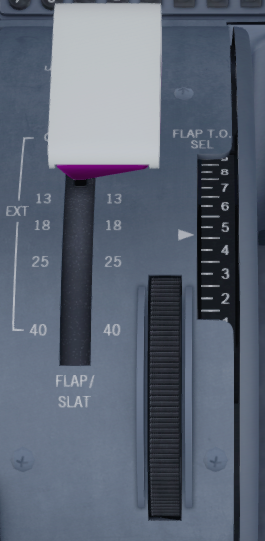
The takeoff flap selection (dial-a-flap) system allows the crew to select a varying degree of flaps between 0 and 20. This is accomplished by moving the thumb wheel until the indicator points to the desired flap setting (pictured left). This system works by moving a mechanical gate in the flaps handle to the appropriate location. The flaps handle can then be moved to that position to achieve the desired flaps angle.
¶ Stall Warning and Stick Pusher
The stall warning system consists of the aural alert, an alert on the PFD, and the stick shaker system. The stick shaker will vibrate the yokes to make the crew aware of the impending stall.
Due to the aircraft’s behavior during a deep stall, a stick pusher system is implemented. If the crew fails to recover a stall or the flight conditions exceed certain limits, the stick pusher system will apply full forward pressure on the yoke. At this time, the STICK PUSHER button will illuminate and the autopilot will disconnect. The stick pusher will continue to apply force until the flight conditions have recovered or one of the STICK PUSHER buttons is pressed.
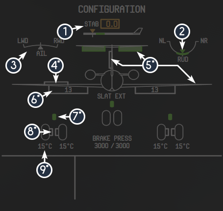
¶ Configuration Synoptic Display
The configuration synoptic display is accessible by pressing the CONFIG SD cue switch.
Note: Elements that show more than once on the display (with different data) are marked with an asterisk.
| ID | Name | Description |
|---|---|---|
| 1 | STAB TRIM | Displays current horizontal stabilizer trim – green band indicates FMS calculated takeoff trim |
| 2 | RUDDER TRIM | Indicates current rudder trim – a green band is displayed to indicate center when on the ground |
| 3 | AILERON TRIM | Displays current aileron trim |
| 4* | SPOILERS | Indicates current spoiler position – displays as a white outlined box when partially deployed and a green filled box when fully deployed |
| 5* | FLIGHT CONTROLS | Displays aileron, rudder, and elevator position - display as white outlined boxes when partially deployed and green filled boxes when fully deployed |
| 6* | FLAPS AND SLATS | Displays current flap and slat status – SLAT EXT appears with slats extended, current flap angle is written in a white outlined box below the wing |
| 7* | GEAR STATUS | Displays corresponding landing gear status – displays hollow white with gear retracted, red filled when unlocked or in transit, and green filled when fully deployed and locked |
| 8* | BRAKE STATUS | Displays white when brake temperature is within reasonable limits – displays amber when outside of limits |
| 9* | BRAKE TEMP AND PRESSURE | Displays brake temperature and pressure – boxed in amber if limits are exceeded |
¶ Fuel System
¶ Overview
Fuel is stored on the aircraft in three tanks – a left main, center, and right main. The main tanks have a capacity of 1,400 U.S. gallons and the center tank has a capacity of 870 U.S. gallons.
The refueling port is on the leading edge of the right wing.
¶ Supply
Each main tank has two fuel booster pumps. In standard configuration, each engine draws fuel from its on-side tank. The center tank has higher pressure than the main tanks, so if there is fuel in the center tank, it will be burned first.
Opening the fuel cross feed and turning the booster pumps on one side off will cause fuel will on the side with the booster pumps to be burned first.
¶ Quantity Sensing
There are two channels of fuel quantity gaging systems powered by different electrical systems. These can be switched by pressing the fuel quantity select button.
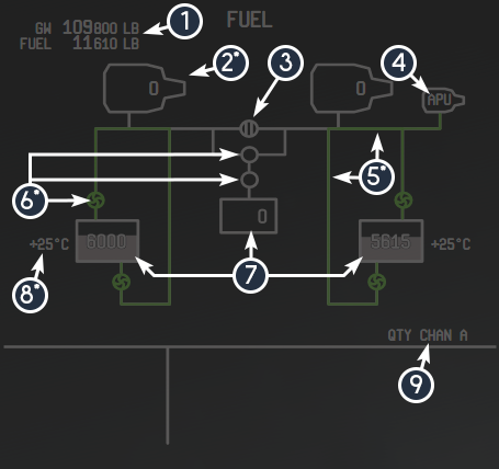
¶ Fuel Synoptic Display
The fuel synoptic display is accessible by pressing the FUEL SD cue switch.
Note: Elements that show more than once on the display (with different data) are marked with an asterisk.
| ID | Name | Description |
|---|---|---|
| 1 | WEIGHT DISPLAYS | Displays gross weight and usable fuel weight |
| 2* | ENGINE FUEL USED INDICATION | Displays the fuel used by the respective engine – cleared by pressing the FUEL USED RESET button |
| 3 | FUEL XFEED VALVE | Displays white if closed and green if open |
| 4 | APU FUEL FLOW INDICATOR | If APU is running, displays an APU symbol and associated flow lines to identify APU fuel source(s) |
| 5* | FUEL FLOW LINES | Displays the current flow of fuel – white if not flowing, green if flowing |
| 6* | FUEL PUMP INDICATORS | Display as a green swirl if powered, amber with a P nearby if it has low pressure, and a white circle if off |
| 7 | FUEL TANK LEVEL INDICATOR | Displays corresponding fuel level – main tanks will display in amber if fuel quantity is low |
| 8* | MAIN FUEL TANK TEMPERATURE | Displays the temperature of the fuel in the corresponding tank |
| 9 | FUEL QUANTITY CHANNEL INDICATOR | Displays the current fuel quantity gaging channel |
¶ Hydraulic System
¶ Overview
The hydraulic system is divided into two sub-systems, a left and right. The left hydraulic system provides pressure to the inboard spoilers, the left reverse thrust clamshell, and the elevator. The right system provides pressure to the outboard spoilers, the rudder, the right reverse thrust clamshell, and the landing gear. Both systems provide pressure to the slats, flaps, nosewheel steering, and brakes.
¶ Pumps
The left and right engine driven hydraulic pumps provide pressure to the corresponding system. The auxiliary pump is an electrical pump connected to the right hydraulic system. It can be used to provide hydraulic pressure when the engine driven pumps are unable to. The transfer pump allows a hydraulic sub-system to be pressurized by an off-side pump.
¶ Hydraulic Synoptic Display
The hydraulic synoptic display is accessible by pressing the HYD SD cue switch.
Note: Elements that show more than once on the display (with different data) are marked with an asterisk.
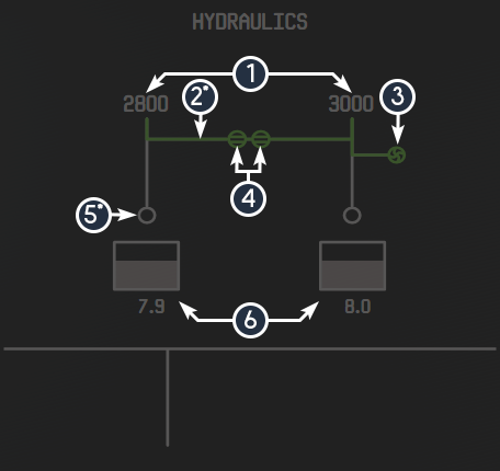
| ID | Name | Description |
|---|---|---|
| 1 | HYDRAULIC PRESSURE INDICATORS | Displays the current pressure in the corresponding system – boxed and amber if outside of normal limits |
| 2* | HYDRAULIC FLOW LINES | Displays green when pressurized or white when unpressurized |
| 3 | AUXILIARY HYDRAULIC PUMP STATUS | Displays as a green swirl if on and a white circle when off |
| 4 | HYDRAULIC TRANSFER PUMP STATUS | Displays the status of the hydraulic transfer pump – green and horizontal when on, amber with "DISAG" nearby if the status does not match the switch, and white and vertical when off. |
| 5* | ENGINE DRIVEN HYDRAULIC PUMPS | Displays as a green swirl when on and pressurized, an amber swirl when commanded on but providing low pressure, and a white circle when off |
| 6 | HYDRAULIC RESERVOIR QUANTITY INDICATORS | Displays current hydraulic reservoir quantity – a cyan line will appear to indicate the initial fill level at engine start |
¶ Ice and Rain Protection
¶ Overview
The ice and rain protection systems consist of several sub-systems. These consist of the wing, tail, and engine cowl anti-ice, air data system and windshield anti-ice, and windshield wipers and anti-fog.
¶ Anti-Ice
The anti-ice system uses air pressure from the pneumatic system. When air-foil anti-ice is activated, an indication of the system(s) in use will appear on the air synoptic display (pictured below).
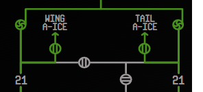
If the engine anti-ice system is activated, the cyan lightning bolt will appear inside that engine’s TGT dial.
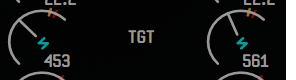
¶ Windshield Systems
The forward three windows have anti-fog and anti-ice. The forward five windows and eyebrow windows have anti-fog.
The windshield wipers operate faster than standard windshield wipers. They have a park mode to return them to the stowed position. They also have a slow and fast mode.
¶ Lighting
¶ Overview
The 717 has standard aviation lights (position, navigation, strobe, beacon, and landing lights). In addition to these, it has a logo light, a wing/nacelle light, and ground flood lights.
In the cockpit, there are integral lights (back lights), flood lights, emergency lights, and the circuit breaker light.
¶ Cockpit Lighting Usage
The cockpit integral lighting also controls back lighting for the radio data displays and the AFS readouts. These displays may become difficult to read at night without integral lighting even if flood lighting is active (pictured left). The rheostat (the larger, lower knob on the cockpit lighting controls) controls the integral lighting.

¶ Emergency Lighting
If the emergency lighting is armed and power is lost to the standard electrical buses, the emergency lighting will activate automatically.
¶ Autoflight
¶ Overview
The 717’s AFS allows the pilot to instruct the aircraft’s computers to handle the aircraft. The autoflight system is very complex and consists of multiple components, which are detailed in the coming sections. A guide to how the AFS controls physically work was provided via the cockpit familiarization diagrams – this section will cover AFS logic and modes.
¶ FMA
The flight mode annunciator is on the top of the PFD (shown below).

The outline around the pitch and roll modes (PITCH and TAKEOFF in the above image, respectively), will be white if the autopilot is disconnected but is able to be engaged. It will be amber if autopilot cannot be engaged, either due to current configuration or because the disconnect button is depressed. When autopilot is disconnected via the autopilot disconnect button, the outline will flash red and the alert will play until the button is pressed again. It will be hidden when AFS is engaged.
The outline around the speed or throttle mode (T/O CLAMP in the above image) behaves the same way for ATS. When disconnected via the ATS disconnect button, the outline will flash red until the button is pressed again.
The location of these modes may change depending on the AFS/ATS configuration, but the behavior is the same.
AFS/ATS MODES
Some AFS modes can be activated by the FMS or by manual pilot selection.
Below is a table of all possible AFS pitch modes.
| FMA | Description | Basic or FMS-Guided | Activation |
|---|---|---|---|
| HOLD | Holds the selected altitude | If magenta, FMS-guided, if white, basic | If FMS-guided, by climbing or descending to the current FMS target altitude – otherwise, usage of the altitude knob |
| VS | Holds the selected altitude | If magenta, FMS-guided, if white, basic | If FMS-guided, set automatically by PROF when needed – otherwise, activated by scrolling the vertical speed knob |
| PITCH | Uses aircraft pitch to hold selected speed | If magenta, FMS-guided, if white, basic | If FMS-guided, set automatically by PROF – otherwise, usage of the altitude knob |
| GS | Provides glide slope guidance | Basic | Set by pressing the APPR/LAND button with an ILS configured |
| FLARE | Provides autoland flare guidance | Basic | Activated automatically by AFS below 50 feet in autoland mode |
| ROLLOUT | Provides basic rollout guidance | Basic | Activated automatically during landing rollout during an autoland |
| GO AROUND | Provides go around guidance | Basic | Set by pressing the GO AROUND button(s) on the throttle(s) |
| FPA | Holds the selected flight path angle | Basic | Set by switching to FPA vertical rate mode and using the vertical speed knob |
Below is a table of all possible AFS roll modes.
| FMA | Description | Basic or FMS-Guided | Activation |
|---|---|---|---|
| NAV | Follows the FMS flight plan | FMS-guided | Activates by pressing the NAV button |
| HDG/TRK | Holds the selecting heading/track (depending on which mode is active) | Basic | Usage of the heading knob |
| TAKEOFF | Provides basic takeoff guidance | Basic | Implicitly set when on ground |
| LOC | Provides localizer guidance | Basic | Set by pressing the APPR/LAND button with an ILS configured |
| ALIGN | Provides runway track alignment guidance during autoland | Basic | Activated automatically when passing below a minimum altitude during an autoland |
| ROLLOUT | Provides basic rollout guidance | Basic | Activated automatically during landing rollout during an autoland |
| VOR1 or VOR2 | Provides guidance to a particular inbound/outbound course to a VOR | Basic | Activated via the NAV RAD page of the MCDU |
| VOR1 or VOR2 CRS | Holds the course previously held by VOR1/VOR2 mode | Basic | Activated automatically either when moving out of range or crossing the VOR |
Below is a table of all possible ATS speed modes. A CLAMP mode indicates that the pilot can manually adjust the throttle position after it has reached the commanded position.
| FMA | Description | Basic or FMS-Guided | Activation |
|---|---|---|---|
| IDLE or IDLE CLAMP | Idles the engines during idle descent | If magenta, FMS-guided, if white, basic | If FMS-guided, activated automatically as needed by AFS, if basic, usage of the altitude knob |
| T/O THRUST or T/O CLAMP | Provides takeoff guidance | Basic | Activated by pressing the AUTOFLIGHT button and advancing the throttles if prerequisites are met |
| THRUST | Holds the selected speed | If magenta, FMS-guided, if white, basic | Activated automatically when speed hold is required – it is dependent on the current pitch mode |
| RETARD | Idles the throttles during landing | Basic | Activated automatically as required |
| CLB THRUST, GO AROUND, MCT THRUST, CRZ THRUST | Holds the corresponding thrust limit | If magenta, FMS-guided, if white, basic | Activated when climbing – if FMS-guided, set implicitly, if basic, usage of the altitude knob |
¶ Armed Modes

Certain modes can be armed prior to engagement. For pitch, GS and PROF can be armed, for roll, VOR, NAV, or LOC can be armed. Once the conditions required to activate the mode have been met, they will be engaged. When armed, they will display in smaller text above the active mode FMA (pictured above).
¶ Vert Alert Logic
During FMS-guided altitude hold, if the aircraft is about to begin climbing or descending, either due to pilot input or removal of a flight plan altitude restriction, “VERT ALERT” will appear above the pitch mode FMA (pictured below).

During this time, the AFS will continue to hold the previous altitude to allow the pilot a chance to intervene. If undisturbed, after the brief delay, the new altitude will become the active altitude and the aircraft will begin its climb or descent.
¶ Protection Modes
If the speed falls below VMIN or goes above VMAX, the ATS will override the current ATS speed mode. It will then either advance or retard the throttle, respectively, until the speed has recovered. In the event of an imminent stall, the stick pusher system will automatically apply forward pressure to the yoke.
¶ Nav and Prof
NAV and PROF are the FMS-guided roll and pitch modes, respectively. They will follow the FMS flight plan and any associated restrictions or limitations. NAV will follow the magenta line on the ND.
PROF, when active, will automatically climb up to a maximum of the selected altitude or descend down to a minimum of the selected altitude, depending on flight phase. PROF will honor altitude restrictions automatically.
¶ PFD AFS Data Display
The PFD will display the selected speed and altitude as a filled white bracket. It will display the preselected speed or altitude as a hollow white bracket (pictured below).
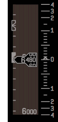
The PFD will display current FMS-guided speed and altitude targets and limits. These are indicated as solid magenta circles for active modes or outlined magenta circles when inactive. For instance, if using EDIT speed, the current ECON speed will be displayed as an outline and the EDIT speed will be solid (pictured below).
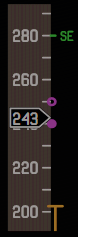
¶ ND AFS Data Display
The ND will display the current flight plan, top-of-climb and top of descent, and altitude or speed restrictions if the data display is enabled. An image of the ND with a flight plan and an altitude restriction at KANDE is shown below. Top-of-climb is indicated as a hollow magenta ball with the cruise altitude displayed adjacent.
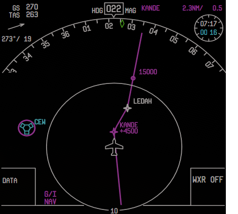
¶ Primary Flight Display
¶ Overview
The PFD displays data used to fly the aircraft including vertical speed, altitude, pitch, bank, heading, and airspeed. A diagram of the PFD is below. The exact appearance of the PFD will vary somewhat based on current configuration and air data status. Some elements, such as the stall warning and ground proximity warning, are not pictured below.
Note: Elements that show more than once on the display (with different data) are marked with an asterisk.
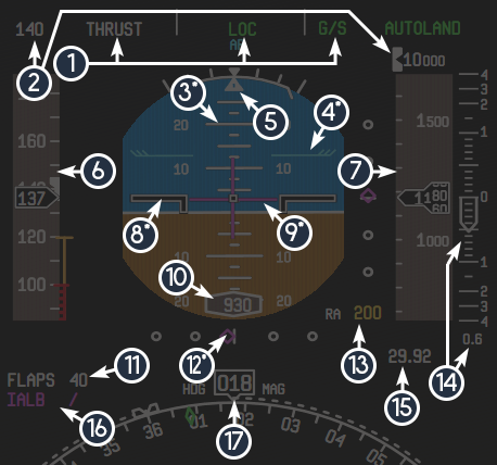
| ID | Name | Description |
|---|---|---|
| 1 | FMA | Displays AFS modes |
| 2 | SELECTED SPEED or SELECTED ALTITUDE | Displays the currently selected AFS speed or altitude |
| 3 | PITCH and BANK INDICATION | Displays current pitch as blue and brown and roll as a rotation |
| 4 | PITCH LIMIT INDICATOR | The blue feathers indicate the pitch associated with the current calculated stall AOA |
| 5 | SIDESLIP, BANK ANGLE LIMIT, and BANK ANGLE | Vertical lines protruding from the represent bank in increments of 10 indicated by the top of the triangle, the bottom of the triangle separates from the top as sideslip increases, and the lines at the edge of the bank range indicate current the bank angle limit |
| 6 | SPEED TAPE | Displays current speed, acceleration as a green line nearby, VMIN and VMAX as yellow poles, VSS and VMO or MMO as red barber poles, flap (FE, F18, F40), slat (SE, SR), and gear (GE, GR) speed limits |
| 7 | ALTITUDE TAPE | Displays current altitude, minimums altitude as a white arrow, and ground altitude as yellow shading |
| 8* | ATTITUDE INDICATOR BARS | These bars, combined with the attitude and artificial horizon behind them, indicate aircraft attitude |
| 9* | FLIGHT DIRECTOR BARS | The flight director bars indicate the AFS commanded pitch and bank |
| 10 | RADIO ALTIMETER | The radio altimeter appears below 2,500 feet AGL and displays current radio altitude |
| 11 | FLAPS and SLATS STATUS | The current flap and slat status – an adjacent upward or downward arrow indicates the flaps or slats are in motion |
| 12* | LOCALIZER and GLIDE SLOPE INDICATORS | The vertical dots indicate glide slope and the horizontal dots indicate localizer – the magenta diamonds indicate aircraft position relative to center, indicated by the line |
| 13 | MINIMUMS | Displays the current minimums altitude and mode (radio or barometric altitude) |
| 14 | VERTICAL SPEED | Displays current vertical speed as an arrow and in thousands of feet per minute below – a white bracket indicates AFS selected vertical speed as appropriate |
| 15 | ALTIMETER SETTING | Displays the current altimeter setting in the unit chosen by the pilot |
| 16 | ILS INDICATOR | Displays the current ILS and, if available, ILS DME |
| 17 | HEADING DISPLAY | Displays current heading, track (if not in track mode), as a green diamond, the AFS selected and preselected headings, and a dotted line to indicate the current direction to the AFS heading |
When certain data input is not available, the PFD will not display dependent on it. If it is off or failed, it will display a failure flag over the data, otherwise, it will just be blank. An image of the PFD without air data is below.
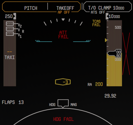
¶ Navigation Display
¶ Overview
The ND provides the pilot with additional data about positioning, waypoint tracking, flight data, and radar overlays. A diagram of the ND is below. Some elements may display differently depending on configuration and may not be pictured below.
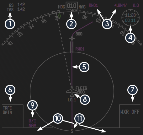
| ID | Name | Description |
|---|---|---|
| 1 | ADDITIONAL SPEED DISPLAY | Displays current ground speed and true airspeed |
| 2 | HEADING DISPLAY | Displays current heading, track (if not in track mode), as a green diamond, the AFS selected and preselected headings, and a dotted line to indicate the current direction to the AFS heading |
| 3 | WAYPOINT DISPLAY | Displays the next waypoint in the flight plan, distance to it, and estimated time en route |
| 4 | CHRONOMETER | Displays current UTC time and elapsed time – cyan if displaying flight time, white if in manual timer mode |
| 5 | MAGENTA LINE | Displays the route and waypoints on the flight plan |
| 6 | DATA MODE DISPLAY | Indicates which data modes have been enabled |
| 7 | OVERLAY/RADAR MODE DISPLAY | Displays which overlay is enabled (weather or terrain) and associated settings |
| 8 | AIRPLANE SYMBOL | Displays the aircraft location – if in track mode, the symbol will rotate to point to aircraft heading |
| 9 | POSITIONING SOURCES | Indicates whether if GPS (G), inertial reference (I), or both (G/I) are providing aircraft position |
| 10 | VOR/ADF DISPLAY | If enabled, this area will display the current VOR or ADF for EIS source 1 and 2 on the left and right, respectively, as well as distance and bearing when applicable – the symbol next to the source will correspond to a pointer on the ND |
| 11 | RANGE DISPLAY | Displays the current map range |
When certain data input is not available, the ND will not display dependent on it. If it is off or failed, it will display a failure flag over the data, otherwise, it will just be blank. An image of the ND without air data is below.
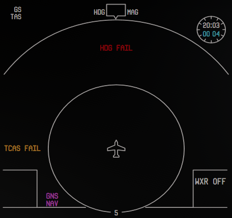
¶ Additional Modes
The ND has 5 modes: MAP (pictured above), PLAN, APPR, TCAS, and VOR. An image of the display in the other four modes and the key differences are below. These are accessible by pressing the associated buttons on the glareshield panel.
¶ Plan Mode
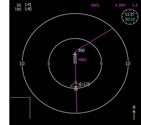
Key differences:
- The ND will display a circular compass with range rings on the sides of the rings
- A north-up arrow will point upward on the bottom right, as the display is always north-up
- The ND will center on the currently selected waypoint when the MCDU is on the F-PLN page, allowing the pilot to preview the flight plan
- The aircraft symbol will rotate according to aircraft orientation in relation to the flight plan
- The radar/weather overlay will be removed
¶ APPR Mode
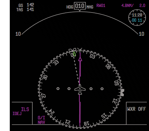
Key differences:
- The map will become a deviation and course pointer for the currently active ILS, if an ILS is selected by the MCDU either automatically from the flight plan or manually by the pilot
- The heading display and associated functionality will move to the inner compass ring
- The data mode display will become an ILS and ILS DME display
- Non-flight plan data and traffic will not be displayed
- The flight plan will not be displayed
¶ VOR Mode
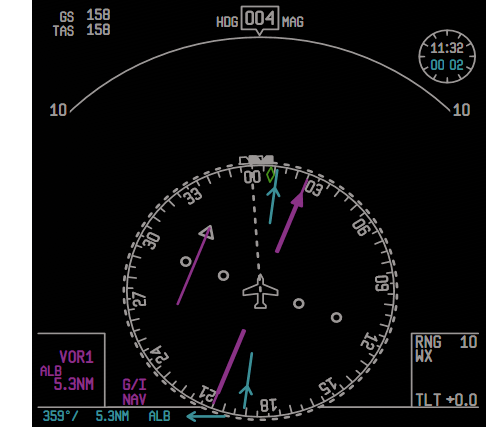
Key differences:
- The map will become a deviation and course pointer for the currently active VOR, if a VOR and course have been selected via the NAV RAD page of the MCDU
- The heading display and associated functionality will move to the inner compass ring
- The data mode display will become an ILS and ILS DME display
- Non-flight plan data and traffic will not be displayed
- The flight plan will not be displayed
¶ TCAS Mode
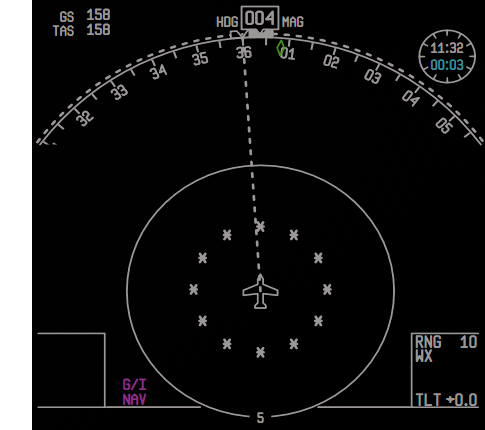
Key differences:
- The Radar and weather overlays will not display
- Non-flight plan data will not be displayed
- All relevant traffic will be displayed
- At 10-mile range selection, a 2-mile range ring will be displayed as asterisks
- When selected, range will be automatically reduced to 10 miles
- The flight plan will not be displayed
¶ System Display
¶ Overview
The SD consists various system synoptic displays, a miscellaneous (MISC), status, and consequences (CONSEQ) page. The system synoptic displays have been discussed in the relevant section of this document already and will not be discussed again here.
¶ Consequences Page
The consequences page is accessible by pressing the CONSEQ SD cue switch. The consequences page displays all alerts that have consequences and the consequence(s) in the adjacent column. An image of that page is below.
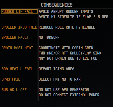
¶ Miscellaneous Page
The miscellaneous page is accessible by pressing the MISC SD cue switch. The miscellaneous page displays any alerts not grouped into other systems, except for maintenance (MAINT) alerts. An image of that page is below.
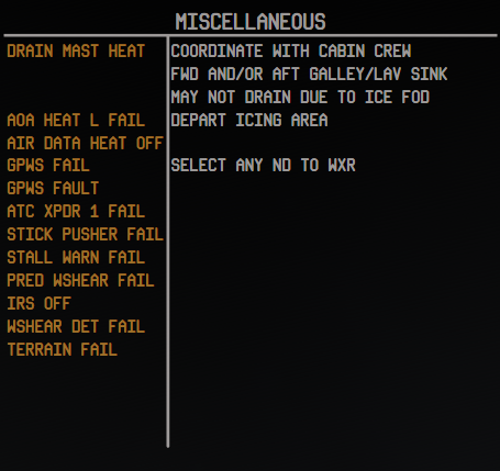
¶ Status Page
The status page is accessible by pressing the STATUS SD cue switch. The status page will display all active alerts, grouped by system, then ordered by priority. This is the only page where MAINT alerts will display. An image of that display is below.
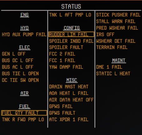
¶ Navigation Display Mode
The SD can display a navigation display in the event that a display unit that the ND should be on has failed. ND SD mode is activated by pressing the ND SD cue switch. If both NDs are functioning and ND SD mode is activated, the SD will display “THIRD NAV DISPLAY NOT AVAILABLE”.
¶ Ground Proximity Warning System (GPWS)
¶ Overview
The GPWS monitors airplane parameters and flight conditions to warn the pilot of unsafe flight patterns. The GPWS will trigger an aural alert and, if required, a flashing amber or red GROUND PROX annunciation on the FMA on the PFD. As each alert was discussed in the CAWS section, this section will more thoroughly explain the underlying logic as appropriate.
¶ Excessive Descent Rate
If the aircraft begins to descend too quickly under a certain altitude, it will cause a GPWS “SINK RATE” warning and display an amber “GROUND PROX” warning on the FMA. If the excessive descent continues into a second, more extreme envelope, the aural warning will become “PULL UP” instruction and a red “GROUND PROX” on the FMA.
¶ Altitude Loss After Takeoff
If the aircraft sinks below 245 feet AGL with the gear retracted and flaps not in the landing range, “DON’T SINK” will be played and an amber “GROUND PROX” alert will be displayed on the FMA.
¶ Unsafe Terrain Clearance
With the landing gear up and the flaps not in landing range, if the aircraft descends below the lower limit of 500 feet AGL, “TOO LOW GEAR” will be played and an amber “GROUND PROX” warning will appear on the FMA.With the landing gear extended, flaps not in the landing rage, and if below 159 knots, when the aircraft descends below the lower limit of 245 feet AGL, “TOO LOW FLAPS” will be played and an amber “GROUND PROX” warning will appear on the FMA.
As speed increases, the terrain closure rate altitude limit increases, up to 1,000 feet AGL at 250 knots or more. Descent below the upper limit will cause “TOO LOW, TERRAIN” to be played.
During departure, if the aircraft sinks more than 75% of the current radio altitude, “TOO LOW, TERRAIN” will be played and an amber “GROUND PROX” warning will appear on the FMA.
¶ Glide Slope Warning
If below 1,000 and above 300 feet AGL and more than 1.3 dots below the glide slope or if below 300 feet AGL and more than 2 dots below the glide slope, the “GLIDE SLOPE” aural alert is played and the BELOW G/S light is illuminated.
¶ Bank Angle Warning
The bank angle warning will cause an aural alert if bank angle exceeds the current limit. The limit increases from 6 degrees at 0 feet and below to 40 degrees at 150 feet AGL. This limit may be reduced by up to 6 degrees depending on current roll rate.
¶ Traffic Alert And Collision Avoidance System (Tcas)
¶ Overview
The TCAS system will attempt to detect and mitigate traffic conflicts. Warnings exist in two levels – traffic advisories (TAs) and resolution advisories (RAs).
¶ Modes
The TCAS/transponder mode control can select test mode, off, transponder on but altitude reporting and TCAS off, transponder on with altitude reporting on with TCAS off, transponder on and TCAS in TA mode only, and transponder on with TA and RA mode on.
RA mode is inhibited below 1,100 feet AGL during departure and 900 feet AGL during approach. Unreasonable RAs are disabled outside of certain altitude envelopes.
¶ Displays
By default, only aircraft that are part of an active TA or RA will be displayed on the ND – this is called part-time display mode. When TRFC mode is active on the ND, all relevant traffic will be displayed.
The TCAS test will look like the image below.
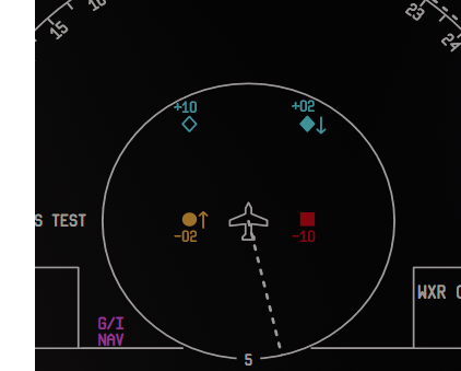
Proximate traffic is displayed as a solid cyan diamond, aircraft involved in a TA will be a solid amber ball, aircraft involved in an RA will be solid red square, and other traffic will be a hollow cyan diamond. The difference in altitude between the aircraft and other traffic will be displayed below the symbol. An upward or downward arrow adjacent to the symbol will indicate if the traffic is climbing or descending significantly.
Current TCAS mode will be displayed on the ND.
During the test, or during an RA, red bands on the PFD will indicate vertical speeds unsafe at that time due to traffic. Depending on the nature of the RA, avoiding certain vertical speeds may not be sufficient to resolve the conflict. In this case, vertical speed should be adjusted to be within the green band. During a TCAS test, the vertical speed display on the PFD will display test bands (pictured below).

¶ Terrain Database And Weather Radar
¶ Overview
The aircraft is equipped with a terrain database and weather radar.
Note: The 717 weather radar requires a compatible third-party weather radar.
¶ Weather Radar
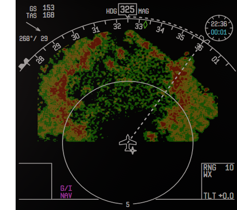
The weather radar can be tested via the knob on the center console. This will cause a test image to be displayed on the ND (if the ND radar overlay is in WXR mode), play the weather related aural alerts, and display associated visual cues.
The intensity of the color of the weather radar returns indicates the intensity of the precipitation. In order, these are green, amber, and red. If in turbulence (WX/T) mode, magenta will indicate turbulence. An image of the ND with weather radar returns displayed is below.
The weather radar will cause a flashing “WXR ON” message to flash on the ND if left on during ground operation.
¶ Terrain Display
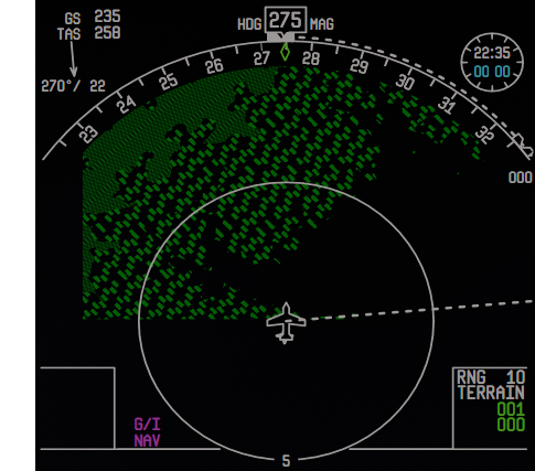
If the ND radar overlay is in TERR mode, a map of terrain will be displayed on the ND. The intensity of the color of the terrain display will indicate the relative threat. Green is non-threatening, amber is possibly threatening, red is 1,000 feet or more above the current aircraft altitude and considered dangerous. An image of the ND with terrain displayed is below (in peaks mode).
A GPWS test will cause a terrain test image to be displayed.
¶ Peaks Modes
With peaks mode active, the profile of the terrain below the aircraft will be displayed, instead of a blank return to promote situational awareness.
With peaks mode active, numbers that represent the peak altitude ceiling and floor are displayed in the radar data display box and change color according to aircraft altitude relative to the terrain. Red and amber are being threats – green indicates safe. They represent altitude by hundreds – for example, an indication of 100 means 10,000 feet, 010 means 1,000 feet, and 001 means 100 feet.
¶ Integrated Standby Instrument System (ISIS)
¶ Overview
The ISIS is a DC-powered standby display that exists to provide pitch, bank, airspeed, Mach number, and altitude to the pilots in the event of a loss of primary flight instrumentation or data. An image of the ISIS is below.
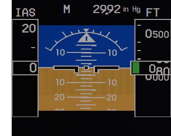
The ISIS has its own altimeter that can be adjusted independently of both the captain and first officer’s altimeter.
¶ Startup And Alignment
Upon initial powerup, the ISIS will initiate a self-test and indicate this on the display. After this, it will begin the alignment process. This test can be initiated by pressing the ISIS align button.
Supplementary Display Information
Display Switching
In the event that a display unit fails, the system will automatically adjust and display the highest priority displays on the remaining screens. An example of this is shown below.
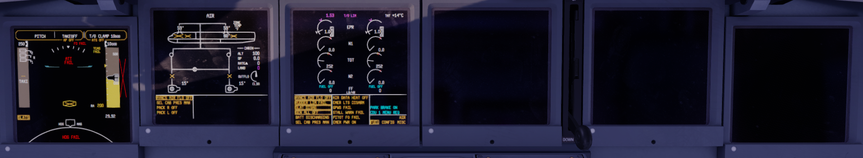
A display can be turned completely off by turning the brightness knob until it clicks into the off position. If all 6 display units are turned off via the knobs, they will all come on at maximum brightness.
Displays During Annunciator Test
If on the ground, an annunciator test will cause various failure flags and messages to appear on the displays. An example of this is below.
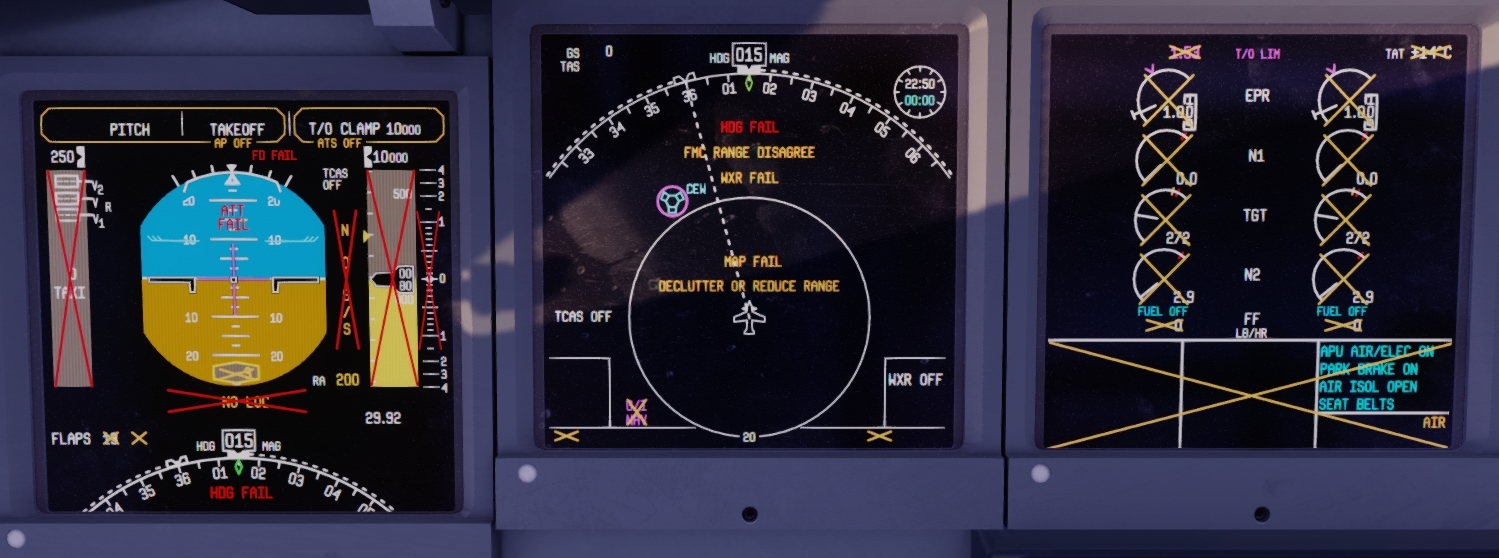
¶ GNSSU And ADIRU
¶ Overview
The 717 is equipped with two ADIRUs and two GPS sensors.
The ADIRUS serve two purposes: to provide air data (pitch, bank, etc.) and inertial navigation information. Backup power is provided to ADIRU 1 and 2 via the airplane battery and an additional backup battery, respectively, in the event of a loss of normal power.
The GPS sensors provide satellite-based position information to the aircraft.
¶ Initialization
The ADIRUs require explicit startup and initialization, known as alignment. To begin powerup and alignment, rotate the respective IRS knob to the NAV position. This will begin the initialization process. To finish the initialization process, a departure and arrival airport must be entered into the MCDU on the F-PLN INIT page and the INITIALIZE IRS function must be activated via the MCDU.
The ADIRU provides different data when off, beginning initialization, finishing initialization, and fully initialized, which causes the PFD and ND to appear different during each stage. The initialization process takes approximately 20 seconds, 3 minutes, or 7 minutes depending on your ADIRU alignment time setting (instant, short, and realistic, respectively). These times will varying depending on aircraft latitude.
The GPS sensors are powered and initialized automatically during normal airplane operation.