¶ Cockpit overview

¶ Forward panel
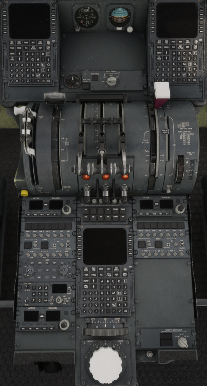
¶ Flight Control Panel

¶ 1. HDG/TRK Changeover Button
Pushing permits alternate selection of either heading (HDG) or track (TRK) to be displayed in the HDG/TRK display window and on the ND. Operation of this button before HDG/TRK HOLD does not affect the window target number. Operation of the button in the HDG/TRK mode compensates the window target to account for any difference in the magnetic heading and track angle but does not change existing control mode or AP/FD reference until the HDG/TRK selector is pushed or pulled.
¶ 2. HDG/TRK Display Window
Shows selected HDG or TRK. Window is blank when the AFS is controlling to the FMS flight plan. At initial powerup the window shows 000 as a preselected value if a valid magnetic heading is not available. If a valid magnetic heading is available at powerup, this is displayed. For powerup while airborne, the current heading is shown as the preselected value.
¶ 3. HDG/TRK and Bank Angle Limit Selectors
HDG/TRK Selector (Inner Knob)
Turn to preselect:
- Rapid rotation causes large changes.
- Resolution for slow knob rotation is one degree per detent.
Pull to select:
- Disengages the NAV mode (if engaged).
- Selects the preselected heading/track and cancels the previous lateral mode. The aircraft follows and captures any selected HDG/TRK while in this mode.
- The display window displays the selected HDG/TRK.
- Once the target HDG/TRK is captured, the system will automatically transition to HDG/TRK HOLD mode and the selector must be rotated, then pulled to select a new heading. During the capture phase, the selected heading/track is changed when the selector is rotated.
Push to hold:
- Disengages the NAV mode (if engaged).
- Causes the aircraft to maintain the present HDG/TRK or, if the aircraft was turning, the heading during the turn plus or minus a small predicted increment to ensure a smooth rollout with no overshoot.
- Cancels VOR, LOC, NAV, and LAND ARMED modes.
- The window displays the capture HDG/TRK.
- Turning the knob in this mode preselects a new HDG/TRK. This requires selection by pulling the knob.
Bank Angle Limit Selector (Outer Knob):
Allows selection of maximum bank angle in 5-degree increments (5 to 25 degrees). In the AUTO position bank angle limits vary with speed (bank limits decrease as speed increases). This selector cannot override FMS-computed bank angle limits. Bank angle limits are displayed on the top of the PFD attitude sphere.
¶ 4. NAV Switch
Push to arm the FMS NAV capture mode or resume FMS lateral control if the capture criteria are satisfied. The NAV armed mode can be cancelled by pushing HDG/TRK hold, selecting APPR/LAND arm, capturing the ILS localizer, or by capturing FMS NAV. After NAV capture, commands are supplied from the FMS. NAV arming is available on the ground once engines are started. NAV guidance is active at 100 feet AGL in FD mode. AP NAV guidance is not available until 400 feet AGL.
¶ 5. IAS/MACH Display Window
The preselected or selected IAS or MACH number is displayed in this window. The range is from 100 to 499 KIAS and M 0.500 to M 0.900. The left end of the display shows IAS or MACH depending on which function is selected. The window shows dashes when the AFS is controlling to the FMS flight plan speed.
¶ 6. IAS/MACH Changeover Button
Pushing the button permits alternate selection of IAS or MACH to be displayed in the window.
¶ 7. IAS/MACH Select Knob
Turn to preselect:
- Rapid rotation causes large changes and slow rotation causes slow changes in IAS/MACH display window.
- Each detent is equal to 1 knot or 0.001 Mach.
If the IAS is displayed, pushing the IAS/MACH changeover button allows display and preselection of the desired cruise Mach. The preselected IAS is retained and displayed when the changeover button is pushed again. At the altitude where the selected IAS corresponds to the preselected Mach, the display and the selected speed reference will automatically change to the Mach mode. The inverse operation (IAS preselection) is available for descent. Changeover to the equivalent Mach or airspeed value occurs automatically at 26,000 feet if no Mach has been preselected.
Pull to select:
- Disengages the FMS speed mode (if engaged).
- The preselected target speed becomes the selected speed.
- The window displays the selected speed.
- The aircraft will follow and capture any selected speed value while in this mode with a pitch or thrust change as appropriate.
- Once the selected speed is captured, the system will automatically revert to the speed hold mode and the IAS/MACH select knob must be rotated, then pulled, to select a new speed. During the capture phase, the selected speed is changed if the knob is rotated.
Push to hold:
- Disengages FMS speed mode (if engaged).
- The aircraft will maintain the present speed plus or minus any small increment if required for a smooth capture.
- The window displays the capture speed.
- Turning the knob in this mode preselects a new speed. The knob must be pulled to select the preselected speed.
¶ 8. FMS SPD Switch
Pushing selects the armed FMS speed, typically an ECON speed, and cancels any selected or preselected speed or Mach number. The IAS/MACH display window shows IAS -- or MACH -- and the FMA speed target and speed control legend changes from white to magenta. Pushing the FMS SPD switch within 10 seconds after preselecting an FCP speed results in editing the FMS-computed speed. The window shows IAS -- (or MACH --) and the PFD FMA speed is the edited FMS speed reference in white (magenta if equal to ECON speed). The FMS SPD mode is disengaged by pushing or pulling the IAS/MACH select knob or by engaging go-around modes. On takeoff, pushing the PROF switch above 400 feet AGL engages PROF and FMS SPD.
¶ 9. FEET/METER Changeover Button
The altitude tape on the right side of the PFD is always in feet. Pushing this button allows the pilot to select feet or meters on the FCP, FMA, and lower right corner of the PFD. When meters are selected the values are preceded by an M. When feet are selected the values ar preceded by an FT.
¶ 10. Altitude Display Window
Displays the selected or preselected altitude for altitude alerting and AP/FD altitude control (except during G/S mode). Range is from 0 to 50,000 feet. Display at initial powerup is 10,000 feet. Window is blank if both air data computer references fail.
¶ 11. Altitude Select Knob
Precision altitude selection increments (one detent) for slow knob rotation are:
- 500 feet above 10,000 feet.
- 100 feet below 10,000 feet.
- If BARO is selected on the ECP, a one-foot precision selection capability permits FCP selection of MDA value.
- 50 meters if METER is selected.
Turn to preselect:
- Sets the altitude reference.
- Window displays the preselected altitude reference.
- Sets FMS clearance ceiling (climb) or floor (descent) when PROF is engaged.
Pull to select:
- Disengages PROF (if engaged) and engages flight level change.
- Disengages vertical speed/FPA or altitude hold modes.
- Flight level change mode sets the ATS to climb thrust or descent idle clamp and AP/FD pitch control to speed. The aircraft climbs or descends directly to selected altitude.
- The aircraft will capture and hold any new altitude selected while in this mode.
- The FCP altitude target becomes the displayed reference on the FMA.
Push to hold:
- Engages altitude capture/hold.
- Disengages PROF (if engaged).
- Disengages VERT SPEED/FPA mode (if engaged).
- Altitude target becomes the current altitude plus or minus a small value required to give a smooth transition to level flight. This target value is displayed in the FCP window, FMA, and on the PFD.
¶ 12. PROF Switch
Push to engage the FMS vertical profile guidance if not previously engaged. After PROF engage, commands are supplied from the FMS (based on inserted flight plan). On takeoff, PROF will not engage until 400 feet AGL. On landing PROF can stay engaged until 50 feet. In takeoff mode, this switch will also engage FMS speeds.
¶ 13. V/S-FPA Changeover Button
Pushing permits alternate display and control of either vertical speed in fpm or FPA in tenths of degrees. When the V/S-FPA is not engaged, alternate function is not selected until the pitch thumbwheel is rotated. After V/S or FPA is engaged, the displayed value is always the selected value.
¶ 14. V/S-FPA Display Window
Displays vertical speed or FPA. Display is blank if V/S or FPA are not engaged. When FPA is selected, the value is in degrees and tenths. When V/S is selected, the value is in fpm.
¶ 15. Pitch Wheel
Rapid rotation results in large changes in the display window. Slow rotation
results in 100 fpm (or 0.1 degree) changes per detent. A vertical speed bug is
positioned on the PFD vertical speed tape corresponding to the selected
vertical speed.
Roll to select:
- Disengages PROF, speed on pitch, altitude hold, and glideslope modes if LAND is not annunciated.
- Display window and target initializes to plus or minus 100 fpm (or 0.10 degree FPA) if engaged in altitude hold. Otherwise, initialization is to current vertical speed/FPA. Subsequent wheel changes result in changes in vertical speed/FPA selection.
- Pushing PROF resumes FMS profile operation at the selected vertical speed as an FMS edit. When the pitch wheel is moved, the AP will cancel the altitude capture mode (if engaged) and will not re-engage in altitude capture until the pitch wheel has come to rest for 2 seconds. The selected altitude will not be captured if the pitch wheel is repeatedly adjusted. In this case, the AP will toggle between vertical speed mode and altitude capture.
¶ 16. APPR/LAND Switch
Push to arm the APPR and LAND modes. LAND ARMED appears in the FMA roll control window. A tuned ILS is required to arm APPR/LAND.
¶ 17. AUTO FLIGHT Switch
Push to engage both ATs and one AP in the FD mode that has been selected. If no FD mode has been selected, the AP engages in HDG/TRK HOLD and either altitude hold (if aircraft about level) or vertical speed hold (if aircraft climbing/descending).
After AP engagement, each push alternates the AP between AP1 and AP2. AP mode is always retained. AP1 or AP2 will appear on the FMA (top of PFD).
On ground, pushing engages autothrottles only. Below 100 feet the AP will not engage. If the AP is engaged above 100 feet, it will remain engaged after passing below 100 feet only in LAND or GA modes.
Operating hydraulic systems required for AP and auto pitch trim are as follows:
- AP1 requires HYD system 2 for flight controls and HYD system 3 for auto pitch trim.
- AP2 requires HYD system 1 for flight controls and auto pitch trim.
¶ 18. AFS OVRD OFF Switches (2)
Push down for emergency disconnect of respective autopilot and autothrottle. In OFF, an amber and gray bar comes into view. Additional FCC functions are affected as follows:
Functions stay on: Altitude alerting, auto ground spoilers, auto pitch trim - LSAS, auto slat extend, elevator load feel, engine trim, flap limiting, FD, LSAS, speed protection - LSAS, stall warning, yaw damp/turn coordination, and windshear guidance.
Functions go off: AP auto pitch trim, Roll control wheel steering, and speed protection - AP & ATS.
¶ EIS Control Panel
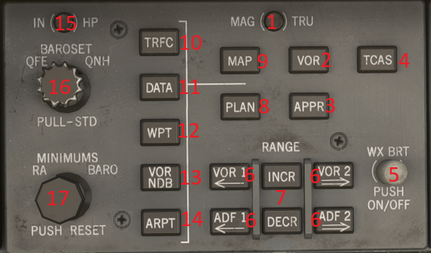
¶ 1. MAG/TRUE Changeover Button
Controls the reference for the heading/track indicator on the ND. If MAG is selected the reference will be magnetic north. If TRUE is selected the reference will be true north.
¶ 2. VOR Mode Switch
Push to select VOR mode on the ND. VOR mode allows the display of full compass rose and a course deviation indicator. VOR display is compatible with MAP and APPR mode display. Weather data may be displayed in the VOR mode.
¶ 3. APPR Mode Switch
Push to select APPR mode on the ND. APPR mode is identical to the VOR mode except that the CDI data source is an ILS receiver. No TO/FROM display is shown in the APPR mode.
¶ 4. TCAS Mode Switch
Push to select TCAS display on the ND with 2 nm range ring and auto range to 10 nm.
¶ 5. WX BRT Knob
Pushing this knob alternates between weather radar and terrain awareness display on ND. Brightness of display is adjusted by turning this knob clockwise or counter clockwise direction.
¶ 6. VOR/ ADF Switch
Controls the bearing pointer display on the ND. Pushing selects or deselects the corresponding source.
¶ 7. Range INCR/ DECR Switch
Controls the function of the map range on the ND. Push INCR to increase the map range from 10/20/40/80/160/320, up to a maximum of 640 nautical miles. Push DECR to decrease map range to a minimum of 10 nautical miles. Map range is displayed on the ND.
¶ 8. PLAN Switch
Push to select PLAN mode on the ND. PLAN mode displays the north-up flight plan with a reference aircraft moving along it. All map data may be displayed in the PLAN mode.
¶ 9. MAP Switch
Push to select MAP mode on the ND. MAP mode allows the display of non-flight plan waypoint, airports, navaids, weather radar data, and bearing pointers.
¶ 10. TRFC Switch
Push to select full-time TCAS traffic display on the ND in MAP, VOR, APPR and TCAS modes. If a full-time display is not selected with this switch, traffic display is inhibited until TA or RA occurs.
¶ 11. DATA Switch
Push to select display of waypoint data on the ND. Waypoint data consists of an identifier, crosstrack deviation, and waypoint constraint data.
¶ 12. WPT Switch
Push to select display (cyan) of non-flight plan waypoints on the ND.
¶ 13. VOR/NDB Switch
Push to select display (cyan) of non-tuned VORs, DMEs, VOR/DMEs, or non directional beacons (NDBs) on the ND. Tuned stations are displayed in white and are not deselectable through this switch.
¶ 14. ARPT Switch
Push to select display of non-flight plan airports normally not displayed on the ND. Runways displayed have at least 5,000 feet of available stopping distance. Origin and destination airports are normally displayed on the ND.
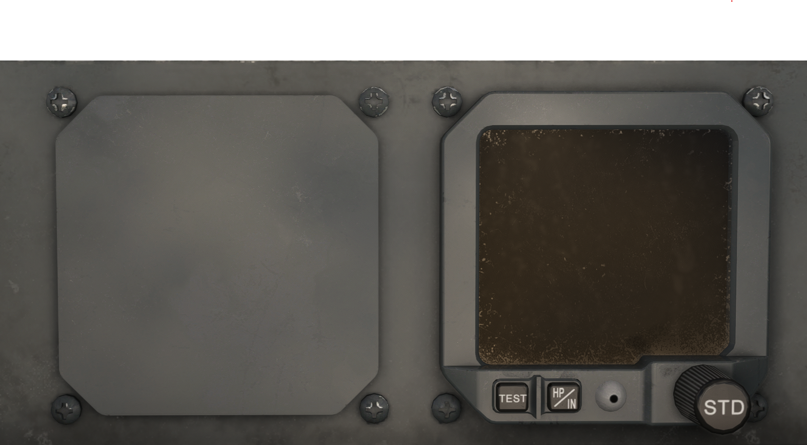
¶ 15. IN/HP Changeover Button
BAROSET values may be in either inches mercury or hectopascals. Pushing this button causes the units to toggle from inches mercury to hectopascals or vice versa.
¶ 16. BAROSET Control Knob
The BAROSET value is adjusted by turning the inner collar.
The outer collar allows the selection of QFE (altitude above station) or QNH (altitude above sea level). Pulling this knob selects the standard BAROSET QNE (29.92 or 1013.2 Hp). BAROSET, QFE and QNH values are displayed on the PFD below the altitude scale.
The QFE is disabled on the TFDi MD-11
¶ 17. MINIMUMS Control Knob
The RA minimums bug is a solid triangle on the left side of the PFD altitude tape. To set the RA bug, turn the inner collar with the knob in RA.
The baro minimums bug is a solid triangle on the right side of the PFD altitude tape. To set the baro bug, turn the inner collar with the knob in BARO. BARO position during initial climb can cause nuisance aural warnings.
Pushing the knob resets the PFD DH alert and silences the aural warning.
¶ Standby Instruments
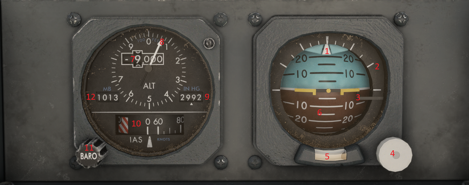
¶ 1. Roll Pointer
Triangular mark indicates center of roll index and center of horizon spheroid. Pointer on spheroid moves in relationship to pointer on roll index indicating amount of roll.
¶ 2.Roll Index
Indexed scale indicates amount of roll left or right. Triangular mark indicates center (zero degrees roll), short tick marks indicate 10 and 20 degrees increments followed by large tick marks indicating 30, 45, and 60 degrees of roll.
¶ 3. Miniature Airplane
Miniature airplane is fixed to the instrument frame.
¶ 4. Caging Knob
Provides a means to bypass the normal electrical erection process of the indicator and orients the internal gyro within 1.0 degrees of an apparent vertical axis. Pulling the knob out will erect the gyro in pitch and roll.
¶ 5. Slip Indicator
Slip and skid is indicated by ball in fluid.
¶ 6. Horizon Spheroid
A plastic sphere with a horizon line engraved in the center to indicate the transition between a climb and a dive condition. The sphere is marked to indicate pitch attitude with a long horizontal line every 10 degrees and a short line indicating 5 degree increments.
¶ 7. ALT Readout
Displays altitude from -1,000 to 50,000 feet in 1,000 foot increments. The zero position in the left hand ten-thousands is indicated by a green square when below 10,000 feet and a red square when below sea level.
¶ 8. 100 Foot Pointer
Indicates altitude against a graduated circular dial, numbered every 100 feet. Pointer makes one complete circle every 1,000 feet.
¶ 9. IN HG Barometric Pressure Display
Indicates pressure, set through the BARO set knob, in inches of mercury.
¶ 10. IAS Indicator
Triangular shaped lubber line indicates non-corrected indicated airspeed.
¶ 11. BARO Set Knob
Sets barometric pressure.
¶ 12. MB Barometric Pressure Display
Indicates pressure, set through the BARO set knob, in millibars.
¶ Gear Handle panel
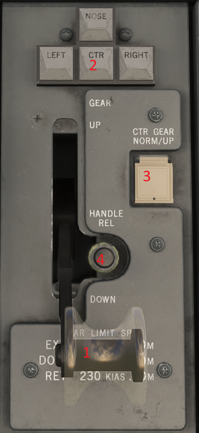
¶ 1. Gear Handle
Mechanically positions landing gear hydraulic control valve for retraction or extension of landing gear. To move handle from UP or DOWN it must be pulled aft. An interlock prevents moving GEAR handle to UP if hydraulic pressure to landing gear trim system fails. A force of 160 pounds may be applied to GEAR handle without causing damage to system.
Failure of the landing gear trim system prevents moving the GEAR handle to UP.
¶ 2. Gear Lights
Green illuminates when:
- GEAR handle is down and landing gear is down and locked.
- GEAR handle is up and landing gear is down and locked via the alternate gear extension lever.
Red illuminates when:
- Landing gear is not down and locked and GEAR handle is down.
- Landing gear is in transit or not in agreement with GEAR handle.
- Any unsafe gear condition exists.
All lights are extinguished when the GEAR handle is up and the landing gear is up and locked.
Red and green illuminate when the respective main gear door maintenance safety hook is installed.
An unsafe condition on one of the two gear indicating systems does not require a mandatory visual inspection. Any green indication indicates a safe gear.
Improved gear lights that are red on top and green on bottom. They are easier to read in direct sunlight
¶ 3. CTR GEAR NORM/UP (switch)
Permits main gear to be extended without extending center gear.
UP prevents center gear from extending when main gear is extended. Center gear warning circuits are inhibited.
If switch is not illuminated, center gear will extend and retract when main gear extends and retracts by means of gear handle. If switch is illuminated, the center gear remains retracted regardless of GEAR handle position.
¶ 4. Handle Rel (button)
Releases anti-retraction mechanism and permits gear handle to be placed in UP in event of ground sensing release mechanism malfunction.
¶ Overhead
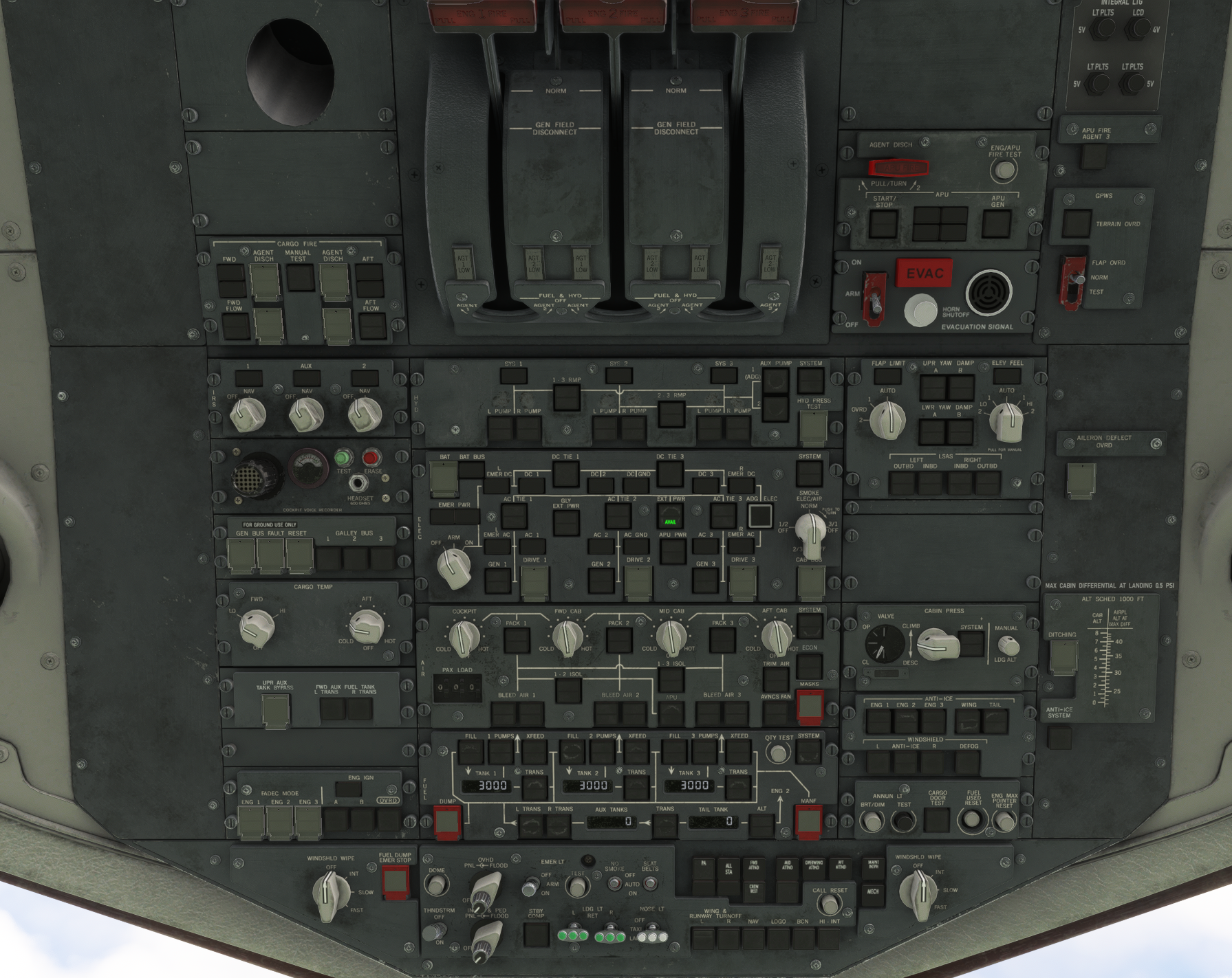
¶ Cargo Fire Panel
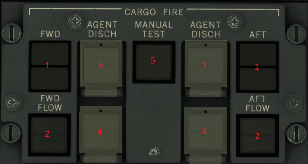
¶ 1. FWD or AFT HEAT/SMOKE light
Illuminates when heat or smoke is detected in lower FWD or AFT (respective) cargo compartment
HEAT OR SMOKE (illuminated)
- Illuminates (steady red) to indicate where heat or smoke has been detected
- Automatically shuts off the respective lower cargo vent fans
¶ 2. FWD or AFT FLOW Light & Switch
DISAG (illuminated)
- Disagreement between switch and operation of the fans
- indicates vent fans in respective compartment have automatically stopped to prevent the fire agent from escaping
Pressing the Switch
- Extinguishes the DISAG light
- Illuminates the OFF light
OFF
- Flow (via vent fans) has been command off by pressing the switch
- Prevents vent fans from automatically starting when heat or smoke is no longer detected
¶ 3. AGENT DISCH FWD 1 / AFT 1 / LOW Switch
FWD 1 or AFT 1 (Illuminated)
- Light flashes, indicating where fire/smoke has been detected
Pressing the switch
- Discharges fire bottle #1 into the respective compartment
- Light extinguishes when smoke/heat is no longer detected
LOW (illuminated)
- Illuminates steady after agent is discharged (appx 28 seconds)
¶ 4. AGENT DISCH FWD 2 / AFT 2 / LOW Switch
FWD 2 or AFT 2 (illuminated)
- Light flashes appx 90 minutes after discharge of FWD 1 or AFT 1 fire bottle (if bottle 2 has not already been manually discharged)
Pressing the switch
- Discharges fire bottle #2 into the respective compartment
- Light extinguishes and LOW light illuminates
LOW (illuminated)
- Illuminates steady after agent is discharged (appx 15 seconds)
¶ 5. CARGO FIRE TEST
The Cargo Fire Test will automatically start when the first IRS selector is moved from OFF to NAV. This test is rearmed to start automatically after each landing, or when electrical power is removed from the aircraft. If an IRS selector is subsequently cycled OFF, then back to NAV (without the accomplishment of a landing or without removing power from the aircraft), the automatic Cargo Fire Test will not start. If, for any reason, the automatic Cargo Fire Test does not after the IRS selector from OFF to NAV, the Cargo Fire Test can be initiated manually by pressing the MANUAL TEST switch.
Initiating the cargo fire test:
- Illuminates the TEST button light
- Illuminates the HEAT / SMOKE lights
- Illuminates all 4 LOW lights
- Illuminates both DISAG lights
- Illuminates the Master Warning light
- Illuminates the Cabin Air System "Smoke" warning light on the Air Panel
- Generates the Alert sound
- Displays CARGO FIRE TEST on EAD
- Displays CARGO SMOKE TEST on SD
During the Cargo Fire Test, the Air Synoptic Display will show the status of smoke and heat detectors. Smoke detectors are normally displayed as solid amber triangles in their respective compartment locations.
Heat detectors are normally displayed as solid amber circles in their respective compartment locations.
¶ IRS Panel
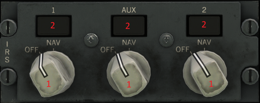
¶ 1. IRS OFF / NAV Select Switch
Moving the IRS selectors from OFF to NAV begins a 10 minute alignment period. During this alignment period, the IRS determines the
approximate current latitude based on calculations using the motion measured from the rotation of the Earth. The calculated latitude is then compared to the present position latitude from the FMS INIT page when the "INITIALIZE IRS" prompt is selected. A significant mismatch between the calculated latitude and the latitude entered from the INIT page will result in a failed alignment. Longitude cannot be calculated during initialization in the same manner. However, the longitude from the last shutdown is stored and used as a reasonableness check during the next alignment. Pressing the "INITIALIZE IRS" prompt when a significant (assumed) longitude position error exists will also result in a failed alignment. Any failed alignment will be indicated by flashing NAV OFF lights, level I "IRU I NO ALIGN, IRU 2 NO ALIGN and IRU AUX NO ALIGN" alerts, and a Master Caution alert.
Be very careful when verifying the INIT page LAT/LONG. The FMS/IRS can, in certain cases, be forced to accept an incorrect position
Although the FMS receives position updates from several sources, the IRS does not receive any enroute updates. If you enter an incorrect present position during initialization, the IRS will operate with this error for the entire flight. Since the FMS receives updates, this won't be a serious problem until you lose both FMSs in Class 11 airspace, and you are left with only IRS navigation. If this occurs, you will have an immediate position error approximately equal to the position error entered during alignment. For this reason, it is very important to ensure that the INIT page present position coordinates are correct prior to selecting the "INITIALIZE IRS" prompt. A rapid alignment (appx 3 mins) may be accomplished by moving the IRS switches from NAV to OFF, then back to NAV within 5 seconds. Realignment will then be initialized with the existing attitude and heading. Velocities will be zeroed.
Movement of the first IRS switch from OFF to NAV (after a landing has occured) will initiate the Cargo Fire Test
¶ 2. NAV OFF (light)
Extinguished
- Alignment is complete, operating in NAV mode
Steady On
- IRS system is either off, in align mode, or has failed
Flashing
- Position not entered within ten minutes, present latitude does not agree with calculated position in the IRU, or the IRU has sensed motion during the alignment phase.
¶ CVR/GEN BUS
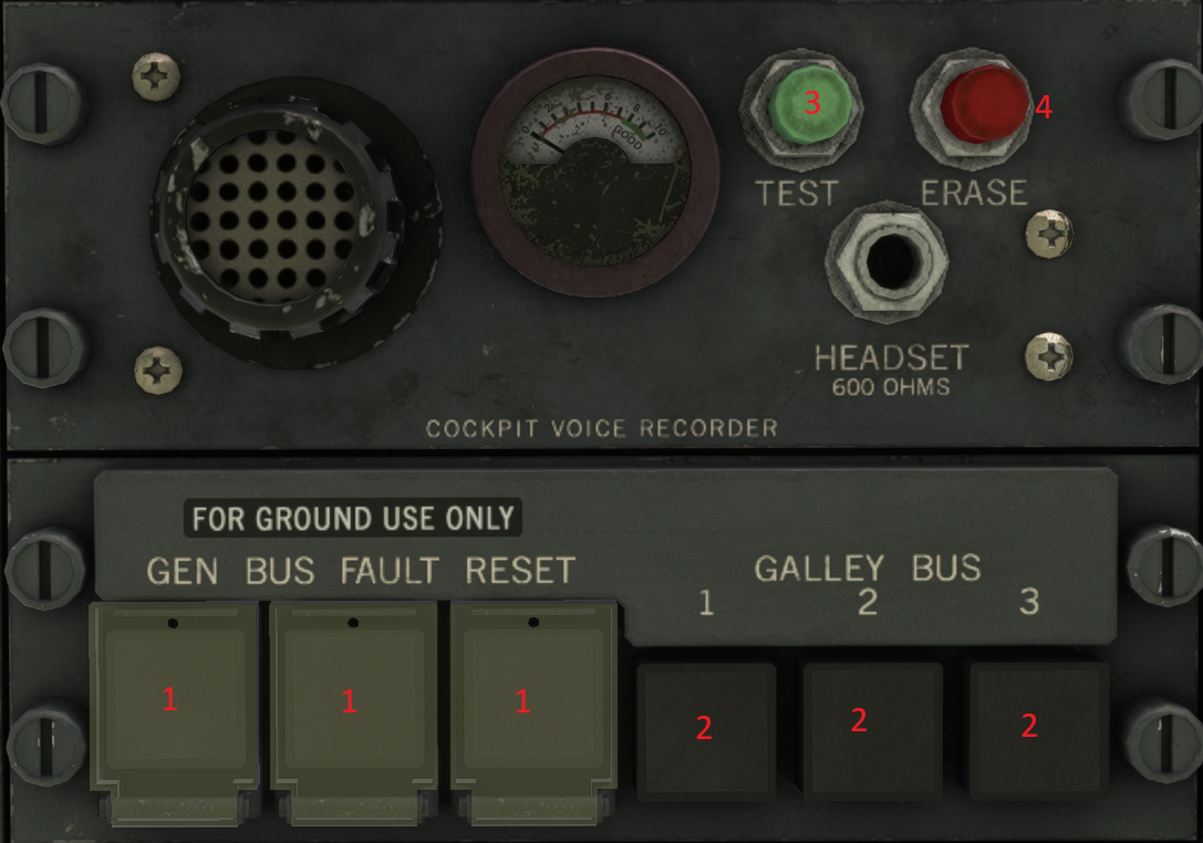
¶ 1. GEN BUS FAULT RESET
Maintenance use only
Not to be used by Flight Crew
¶ 2. BUS FAULT (illuminated)
- Switch is used to reset the associated Generator Control Unit
¶ 3. CVR TEST (pressed)
- Minimum of level 8 during test
¶ 4. ERASE (Pressed)
- Can only be accomplished on ground with parking brake set
¶ Misc

¶ 1. ANNUN BRT/DIM
Used to control annunciator light intensity
¶ 2. ANNUN TEST
Used to test all annunciator lights in the cockpit. Pressing button will illuminate all lights. Holding button (approximately 5s) will initiate the CAWS test.
¶ FADEC
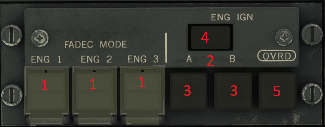
The FADEC controls:
- Engine acceleration to idle speed during start
- Acceleration and deceleration limiting
- Automatic control of available thrust
- Minimum / Approach Idle speeds during descent
- Compressor airflow control
- Thrust control as a function of throttle position and thrust reverser lever
- Protection from exceeding N1, N2, internal pressures, and max thrust lmts
The FADEC system utilizes dual channel ECU (GE) or EEC (P&W) units, each having two CADC inputs. Cross-talk between channels allows for normal operation with the failure of one ECU or EEC channel. Each ECU or EEC is selfpowered by an N2 driven PMA (Permanent Magnet Alternator). The PMA has dual windings, each powering an individual ECU or EEC channel. 28vDC power is also available on all GE, and some P&W powered MD-11s, from its respective DC bus in the event of a failure of both PMA windings. The failure of both EEC/ECU channels, or the failure of both windings of the PMA (if not equipped with 28v backup power), will cause an automatically controlled engine shutdown to occur.
¶ 1. ALTN
FADEC uses two CADC inputs to each
EEC or ECU channel. The loss of one CADC
input to an ECU or EEC channel has no affect on
normal operation. When both CADC inputs to an
EEC or ECU channel have been lost, FADEC
automatically switches to the other EEC or ECU
channel. If both CADC channels have been lost to
both EEC or ECU channels, SELECT and ALTN
will illuminate. When this condition exists, the
FADEC uses the last CADC input it sensed to
calculate thrust. When ALTN is pressed, SELECT
will extinguish and ALTN will remain illuminated.
Alternate mode of the FADEC utilizes an internal,
fixed schedule to determine thrust level for the
selected throttle position. This internal schedule
may cause thrust to increase, but will never cause
thrust to decrease. With P&W engines,
autothrottles are not available when operating in
the ALTN mode.
Pushing throttles through overboost bar will also cause FADEC to revert to ALTN mode.
¶ 2. Ignition Pwr Sources
Ign A is powered by L emergency bus, and is required for dispatch. Ign B is powered by R emergency bus.
(“A” Odd flt # / “B” even flt #)
¶ 3. ENG IGN OFF (Illum).
-No ignition source is selected and no power is being supplied to the ignitors.
¶ 4. ENGINE IGNITION SWITCH (A & B)
A (or B) – Switch selects ignition in the Auto mode. A (or B) Illuminates when ignition A (or B) is selected.
Selecting Ign A or B will:
- Extinguish the ENG IGN OFF light
- Supply 28v DC power to each engine start switch
- Arm ingitor A or B
- Command APU to 100%
- Prepares EAD for display of start indications
- Configures fuel system for engine start
- Arms the engine driven hydraulic pump test
- Packs shut off (packs turn back on if engine not started within 2 mins after selecting). Packs turn back on after engine is started.
MANUAL (illuminated)
Auto ignition control has failed, and the engine
ignition that is selected (either A or B) is commanded
on continuously until the pilot chooses to assume on /
off control manually.
Continuous Ignition (Auto mode)
Automatically on for start, takeoff (On when > 70o
throttle resolver angle; Off when slats retracted),
landing (On when slats, flaps or gear extended; Off 1
minute after ground shift) and 60 seconds after
engine A/I is turned on.
¶ 5. OVRD Switch
Pressing switch powers both ignitors on all engines and bypasses auto ignition control.
OVRD ON
- Illuminated when on
¶ Engine Fire
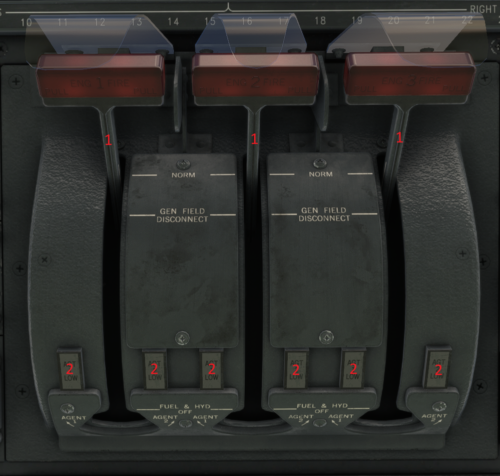
¶ 1. ENGINE FIRE HANDLES
- Illuminates for an overheat or fire in the respective engine nacelle
- Remains illuminated until the fire / overheat no longer exists
Simultaneously to fire handle illumination, the following occurs:
- Fuel switch illuminates red for the respective engine
- Master warning light illuminates
- EAD annunciation
- Fire bell sounds
Pulling the fire handle accomplishes the following:
- Silences alarm (if not silenced by pressing the master wrng switch)
- Disconnects the generator field
- Closes the Hyd Fire Shutoff Valve
- Closes the Fuel Fire Shutoff Valve
- Shuts down the associated Air System (if Air Sys in Auto mode)
Rotating the Fire Handle (after pulling)
- Discharges the respective agent bottle into the engine nacelle
¶ 2. AGT LOW (1 or 2) light
Illuminates when respective bottle is discharged (battery bus powered)
¶ 3. FUEL SWITCHES
- Illuminates red when respective fire handle illuminates
- Remains illuminated if the fire warning still exists
- With the Fire Handle pulled and the fire warning terminated, this light stays illuminated until it is moved to OFF
¶ Hydraulic

Min Hyd quantity for dispatch
Sys 3 = 6 gals, sys 1 & 2 = 4.75 (5.25 desired) – Loss of fluid in system 3 down to 4.75 gals will close a oneway check valve, preventing total fluid loss from leak in the tail section.
HYD QTY LOW alert
- when qty reaches 4.74 on the ground, or 2.5 in flight
HYD SYS FAIL
- alert when hyd qty reaches 1 gallon
Non-Reversible Motor Pumps
2-1 NRMP provides hyd power for the upper rudder and stab trim with a loss of Sys 1 hydraulics. 3-2 NRMP provides hyd power for the lower rudder with a loss of Sys 2 hydraulics. No fluid is exchanged through the NRMP’s. Fluid is provided from alternate reservoir systems referred to as compensators.
Autopilot use with hydraulic
system loss:
Lose 1 – Use A/P 1
Lose 2 – Use A/P 2
Lose 3 – Use A/P 2 *
- Autopilot 1 uses hyd sys 2 & 3
- Autopilot 2 uses hyd sys 1
If using A/P 1 with a loss of Sys 3, A/P will not be able to control stab trim.
Enhancement “Sioux City” Valve
Valve located near pressure bulkhead in HYD System 3 protects hyd fluid forward of the valve. Closes at 4.75 gals Enough Sys 3 fluid will be retained to allow pitch & roll control through use of horizontal stab trim and lateral controls powered by Hyd system 3.
Controls Avail.:
- Ailerons
- Spoilers
- Stab Trim
¶ 1.1-3 & 2-3 RMP (Reversible Motor Pump) switch
Switch Controls the RMP shutoff valves when hydraulic system is in Manual mode
RMP(s) On (ON illuminated) RMP(s) OFF (ON Extinguished)
If in Manual Mode -Hyd reservoir quantity < 1 gal on either side of RMP
-Switch pressed and Respective RMP has been commanded on -ADG deployed with ADG electric switch off
If in Auto Mode -Cruise flight with two hyd systems pressurized
-Any N2 falls below 45% during taxi, takeoff or landing -Engine start in flight
-Eng driven pumps unable to maintain pressure during taxi, T/O or landing
-Auto slat extend DISAG
-Loss of second engine or second hyd system during cruise phase of flight -Disagreement between valves and commanded position
-When selecting Manual during Auto operation -RMP commanded OFF & pressure still exists in system
¶ 2. SYS (1,2,3) PRESS
Illuminates if hyd pressure is too high or too low (<2400 or >3500). Extinguishes when press is normal
¶ 3. L PUMP / R PUMP Switches (Systems 1,2,3)
The L PUMP switch commands the respective engine hyd pump On/Off when operating in Manual mode. The R PUMP switch
commands the respective engine hyd pump Armed/Off when operating in manual mode. Both switches for the respective engine are disabled in Auto mode. With the engine running and hydraulic systems operating normally, the respective engine driven L PUMP is ON, and the R PUMP is armed (ready to operate in the event of a L PUMP malfunction). Right pumps are tested at engine start. FAULT (illuminated) When low pressure (<2400) or high temperature (>245o in pump case drain) is detected. In auto mode, a failure of the primary (left) pump will cause the secondary (right) pump to start.
OFF
- Extinguished when pump is operating normally, and respective system is pressurized. Pumps are off (and OFF is illuminated) when pump or system pressure is too low or too high, when pump or system temperature is too high, when fluid qty is low (<2.5 gals), during engine start and when fire handle is pulled. When electrical power is lost, engine pumps fail to ON.
- OFF also illuminates when pump is manually commanded off (which only possible when operating in manual mode).
¶ 4. AUX PUMP (1 & 2)
Switches command AUX PUMP(S) on or off
when operating in Auto or Manual mode.
ON
- Illuminates when respective aux pump is on for the purpose of pressurizing hydraulic system 3. The Aux pumps can be commanded on automatically by the HSC, or commanded on manually by the pilot. The #1 aux pump is also commanded on prior to engine start when the AUX HYD PUMP 1 switch on the Brake Control Panel is pressed - then automatically shuts down when the first fuel switch is turned on.
¶ 5. HYD PRESS TEST
Initiates hyd pressure test. Switch operates only in Auto mode.
TEST (Illum.)
- Indicates hyd test is in progress. Tests RMP’s and Aux pumps If Aux Pump pressed while test is in progress, the test stops.
¶ 6. SYSTEM SELECT / MANUAL switch
Two channels – pressing once selects manual. Pressing a second time selects second auto channel.
SELECT (illuminated)
- System has automatically switched to manual. Pressing switch locks system in manual mode (SELECT no longer illuminated).
MANUAL (illuminated) - System operating in manual mode
- MANUAL flashes if switch has been pressed that has no effect in auto mode.
¶ Electrical
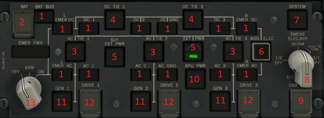
Electrical Priority for the AC gen bus is:
- Associated IDG
- APU Gen
- AC Tie Bus (Ext or IDG)
Electrical Priority for the AC Tie bus is:
- Ext Pwr
- Any IDG
¶ 1. BUS OFF lights (13 total)
OFF
- Illuminates if associated bus is not powered
¶ 2. BAT Switch
- Connects/Disconnects Batt from Bat bus and charger
- Switch operates in Auto or Manual
ON (Off light extinguished)
- Batt powers Batt Bus (if AC pwr is not available)
- Batt charger allowed to charge, except when:
- -EMER pwr is in use
- -Inverter powered refueling is being used
- -AC power is not present at charger input
OFF (Off light illuminated)
- Batt disconnects from Bat Bus
- Charger is inhibited
- Auto transfer of EMER pwr is inhibited
¶ 3. AC TIE Switch (1, 2, 3)
In Manual mode, Switch controls the Bus Tie Relay.
ARM illuminates in Auto mode.
ARM
- Illuminates when bus tie relay is open and switch is in ARM position
OFF
- Bus tie relay is open and switch s in the OFF position. Busses are solated from Tie Bus.
OFF & ARM Extinguished
- Bus Tie elay is closed
¶ 4. DC Tie Switch (1 & 3)
Switch controls RCCBs in Man mode
Switch inop in Auto mode
OFF
- DC Tie Bus is
open due to:
- Switch pushed (Man)
or - RCCB protective trip
¶ 5. EXT PWR Switch
AVAIL
- Illuminates when EXT pwr is available.
ON
- When AVAIL is illuminated, pressing switch provides external pwr to the AC Tie Bus.
- When AC Tie Bus is powered, ON illuminates.
- Pressing switch again disconnects external pwr.
¶ 6. ADG ELEC Switch
Extinguished (default mode after ADG is deployed)
- ADG will power L EMER AC bus and AUX hyd pump 1.
ON
- ADG pwrs L & R EMER AC & DC busses, batt chrgr and batt bus. (Aux hyd pump no longer pwrd)
¶ 7. System Select Switch
Allows selection between Auto and Man
SELECT
- will illuminate if system reverts to Man.
- Pressing the switch extinguishes SELECT, and locks the system in Manual.
- MANUAL – System operating in Man mode
¶ 8. SMOKE ELEC/AIR Switch
Isolates Elec & Air (for smoke) in Auto or Manual modes
NORM
- Elec/Air ops normal
3/1 OFF
- Gen 3 sys & Pack 1Air sys OFF
- ECON mode OFF
- EIS CRTs to full bright
2/3 OFF
- Gen 2 sys & Pack 3 Air sys OFF
1/2 OFF
- Gen 1 sys & Pack 2 air sys OFF
- EMER pwr transfer inhibited
¶ 9. CAB BUS
OFF (Illuminated)
- Pwr is removed from Cargo Loading bus and Cabin AC Grnd Service Bus
¶ 10. APU PWR Switch
Switch starts APU (if not already started from APU panel) and powers GEN busses.
AVAIL
- Flashes until APU reaches 95% & power is OK. Steady when OK for power transfer.
ON
- Illuminates when APU is powering a bus (any bus).
¶ 11. GEN Switch (1,2,3)
Switch resets generator in manual mode.
Auto mode will perform this function automatically, if req’d.
OFF
- Illuminates when GCR is tripped open (no pwr being supplied).
ARM
- Illuminated when GCR is closed and generator relay is open. System is ready for pwr transfer.
¶ 12. DRIVE Switch (1,2,3)
Switch disconnects IDG in Auto or Man modes
Fault: illuminates when:
- IDG oil temp high
- IDG oil press low
- IDG oil temp diff. out of limits
IDG disconnect req’d
DISC
- Press to disconnect IDG.
- Successful disconnect is indicated by illuminated DISC
¶ 13. EMER PWR OFF/ARM/ON Selector
Controls Batt transfer to L EMER AC/DC bus
Selector operates in Auto or Manual mode
OFF (also illuminates OFF light)
- Batt / Inverter inhibited from supplying pwr to L EMER AC & DC Busses
ARM:
If normal pwr is lost, batt will automatically supply pwr to:
- L EMER DC bus
- L EMER AC bus (through static inverter)
- ON light illuminates if auto transferred to EMER pwr.
For auto transfer to occur:
- Batt switch must be ON
- SMOKE/ELEC/AIR selector not in 1/2 OFF
ON (also illuminates ON light)
- L EMER AC & DC being powered by Batt / Inverter
¶ Air

¶ 1. COCKPIT / COURIER / CARGO Temp
65o to 85o range – Center position is 75o
OFF
- Respective trim air valve is closed (cold)
- Zone TEMP OFF alert appears
COLD (full)
- All 3 packs driven to full cold
HOT
- Trim air is added
¶ 2. PACK Switch (1,2,3)
Controls respective pack flow valve in manual mode – Switch inhibited in Auto
FLOW
- Amber if packs are on, but flow is insufficient, or flow is present with packs commanded off.
OFF
- Illuminated when pack is commanded off manually (Ram Air Door is commanded closed)
¶ 3. TRIM AIR Switch
Opens/closes Trim Air Press
Regulator Valves in manual mode
OFF (pushed in Manual Mode)
- Trim Air PRVs manually turned off
- Prevents hot air from entering Trim Air Manifold
AVNCS OVHT
- Amber when overheat is sensed in avionics compartment.
- Assumes trim air duct rupture
- Auto closes trim air PRVs
Must be reset by maintenance
Pushing a 2nd time (while illum.)
reopens the AC shutoff valve.
¶ 4. Air SYSTEM Select Switch
Allows selection between (2) Auto channels and (1) Manual channel. When functioning properly, the Air System defaults to an Auto Channel. Pressing the switch then selects the Manual mode. Pressing the switch again selects the other Auto channel.
SELECT
- Illuminates if system detects a malfunction, and reverts from Auto to Manual mode.
MANUAL
- Illuminates if Manual mode has been selected by pressing the switch.
- Flashes if system is in auto and any switch on Air Panel is pressed that has no effect in auto mode.
¶ 5. BLEED AIR (1,2,3) PRESS / OFF Switch
Controls the Eng bleed valve in the manual mode
Operates in parallel with, & identical to the MAN TEMP HI switch
PRESS (illuminated)
- Air press low (< 11psi)
OFF (Pressed in Man)
- Bleed valve is manually commanded off
¶ 6. ECON Switch
Works in Auto or Manual mode
Starts/Stops Econ op’s of packs
ESC automatically turns ECON mode on/off as req’d for flt conditions.
Unless otherwise needed, Air system normally operates in ECON mode with packs operating on low volume.
OFF
- ECON manually selected off
- Will not illuminate if ESC automatically selects ECON off.
CAB ALT
- Illuminates when cabin altitude is greater than 9500 ft.
¶ 7. BLEED AIR (1,2,3) MANF / TEMP HI Switch
Controls the Eng Bleed valve in Manual mode
Operates in parallel with, and identical to the BLEED AIR PRESS Switch
MANF (Auto or Manual)
- Illuminates when excessive temperature is detected in any compartment in which a pneumatic manifold is routed. Indicates a failed or leaking manifold.
TEMP HI (Auto or Manual)
- Illuminates when excessive bleed air temperature is detected downstream of the precooler
In Auto, the respective Eng Bleed valve closes to remove bleed air from a damaged system.
¶ 8. 1-2 ISOL / 1-3 ISOL Switches
Open/close respective ISOL
valve when sys is in Manual.
Inhibited in Auto mode
ON (Switch pressed in Manual)
- ISOL valve is commanded open
DISAG
- Illuminated when ISOL valve is not in commanded position.
- Light inhibited for 10 secs in Auto mode. In Manual, illuminates when valves are in transit.
¶ 9. APU Switch
Opens & closes APU bleed air load valve
ON
- APU valve is selected open (if Air in Auto. ISOL valves 1-2 & 1-3 are auto controlled).
USE ENG AIR
- APU air is ON and diff press is > 1.3 PSI (acft is beginning to pressurize)
¶ 10. AVNCS FAN Switch
Starts/Stops override of the avionics exhaust fan and venturi shutoff valve in the manual mode.
FLOW Illuminates if:
- Cooling airflow through the avionics is below normal
- Cabin inflow is insufficient for pressurization
- Cabin altitude greater than 10,000’
Auto closes venturi & fan turns on
OVRD (pressed in Manual mode)
- Starts avionics exhaust fan
- Closes avionics cooling outflow venturi
¶ 11. NO MASKS
Illuminates if cabin approaches 15,000 ft, and masks in crew rest module have not (auto) deployed.
Pressed & held for 3 seconds deploys the masks
¶ Fuel

Fuel Capacity
Tank 2 = 64,000 lbs
Tank 1 / 3 = 40,500 lbs
U/L Aux = 98,100 lbs
Tail = 13,100 lbs
Total = 256,800 lbs
¶ 1. Tank 1,2,3 FILL Switches
Switch opens the respective Fill valve in Manual mode
1st Press:
- In Manual mode, Arms the Fill valve for as long as it is held
- Remains armed after release under these conditions
- -Tank 2 Fill valve remains armed if any Upper Aux tank pump is on
- -Tanks 1/3 valves remain armed if tank 2 > 40,000 lbs
2nd Press
- Disarms the Fill valve
ARM (illuminated)
- Fill valve armed to accept transferred fuel
FILL (illuminated)
- Fill valve open and accepting transferred fuel
¶ APU
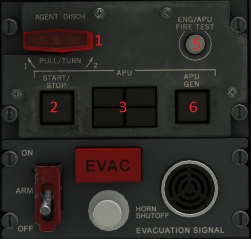
APU In-Flight Parameters:
Start Up to 25,000 ft.
Run Up to 30,000 ft (electrical only)
APU Auto Shutdown:
-Overspeed or loss of N1or N2 signal -High EGT or loss of EGT signal
-Low oil pressure or high oil temp -No light-off during start, or slow start
-Reverse flow in bleed air system -Inlet door not open, or power failure
-Fire warning -Loss of DC power
¶ 1. AGENT DISCH Fire Handle
Illuminates when an APU fire is detected, and automatically commands:
- Master Warning lights on
- EAD alert
- APU FIRE illuminates (red) on APU Fire Handle
- Fire Horn sounds near external APU Panel (nose gear area)
- APU shuts down
- Aural Warning sounds
- If equipped with 3rd, dedicated fire bottle, it will automatically discharge
Pulling the APU Fire Handle:
- Emergency APU shutdown
- Fire extinguishing agent is armed to discharge
- APU Generator disconnects / de-energized
- APU Fuel Valve closes
- #2 Engine bleed valve closes
Rotating the handle (after pulling):
- (Clockwise) Discharges fire bottle #1 (shared with engine 2)
- (Counterclockwise) Discharges fire bottle #2 (shared with engine 2)
¶ 2. APU START/STOP Switch
Starts and stops the APU manually
If this switch is used to start the APU, it must also be used to shut it down
ON (Switch pressed and ON illuminated)
- Flashes when APU is starting. Steady when started and ready for use
- If APU shuts down due to fire, light flashes until the switch is selected to OFF
OFF (When pressed)
- Illuminates steady when APU shutdown is initiated
- APU bleed valve automatically closes
- APU shuts down 90 seconds after no longer supplying air
- Remains illuminated until shutdown is complete
¶ 3. APU FUEL/FAIL/DOOR Status lights
FUEL (illuminated)
- Fuel pressure is too low
DOOR (illuminated)
- APU inlet door not fully open during start
- APU inlet door not fully closed after shutdown (The door begins to close appx 60 seconds after shutdown. Shutdown occurs appx 90 seconds after APU is no longer supplying air. The door takes appx 12 seconds to close)
FAIL
- APU has failed, and start is not possible
¶ 4. APU FIRE AGENT (1,2) (Low Light)
- Associated with APU fire
- bottles 1 & 2 that are shared with engine 2. These lights are not installed on all MD-11s
LOW (illuminated)
- Associated fire bottle has been manually discharged
¶ 5. ENG/APU FIRE TEST Button
When pressed:
- ENG and APU Fire Handles illuminate
- Fuel Switches illuminate
- Both Master Warning lights flash
- Fire Bell and aural warning tone sounds
- ENG 1,2,3 and APU FIRE alerts display
- ENG FIRE voice warning sounds
- (6) Eng FIRE AGT LOW lights and (2)
APU FIRE AGENT LOW (if installed) illuminate
When on battery power only, the Master
Warning lights, Fire Bell and FIRE alerts
will not activate
¶ 6. APU GEN Switch
Pressed
- Resets APU Gen if Elec in manual mode
OFF (illuminated)
- Gen on speed, but malfunction has occurred
¶ 7. APU FIRE AGENT 3 DISC/LOW Switch
This switch is only installed on aircraft that have the third, dedicated APU fire bottle installed.
LOW (illuminated)
- Respective fire bottle has been automatically or manually discharged
DISC (illuminated)
- APU Fire Handle has been pulled
DISC Switch Pressed
- Manually discharges fire bottle 3 (if auto discharge fails – APU fire handle must be pulled before switch is pressed)
¶ LSAS
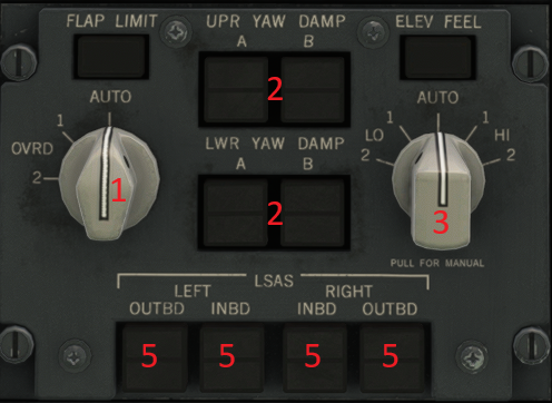
LSAS provides:
- Pitch Attitude Hold and Automatic Pitch Trim – With no force
on the control column, and bank angle less than 30 degrees,
LSAS holds the current pitch attitude. LSAS holds this attitude
by deflecting the elevators as much as 5 degrees. The
horizontal stabilizer is automatically adjusted to relieve the
sustained elevator deflection and maintain a full 5 degree
elevator authority. - Pitch Attitude Limiting – LSAS maintains pitch attitude to less
than 10 degrees of dive, or less than 30 degrees of climb. - Pitch Rate Damping – Increases the apparent static stability to
reduce the chance of over-control in pitch. It is active
throughout the flight envelope. 100% of max damping is
available above 20,000ft, decreasing linearly to 30% below
16,500 ft. - Speed Protection – If the autopilot is not engaged and the
autothrottle is not available (or able to maintain a safe speed),
LSAS Speed Limiting will engage to provide overspeed or
stall protection. LSAS overspeed protection is accomplished
by changing pitch. LSAS does not provide flap, slat or gear
overspeed protection. - Stall Protection – At 75-85 pct of the angle of attack required
to activate the stick shaker, the LSAS stall protection engages.
LSAS reduces pitch until the AOA is sufficiently reduced. - Pitch Attitude Protection and Positive Nose Lowering - During
takeoff rotation, LSAS provides Pitch Attitude Protection
(PAP) to reduce the possibility of a tail strike. During landing,
after spoiler deployment is commanded, LSAS initiates
Positive Nose Lowering (PNL) to assist in transitioning the
nose wheel to the runway after main gear touchdown.
LSAS is off when: - The autopilot is engaged
- Below 100 ft RA, except active for pitch attitude protection
during takeoff and positive nose lowering during landing. - Bank angle exceeds 30 degrees
- During manual trim operation
- Pilot can override LSAS if, when below 1500 ft., more than
appx 2 lbs. of pressure is applied to the control column; or,
when 10-15 lbs of force is applied while PAP or PNL is active.
The pilot may counteract the LSAS overspeed or stall protection
by using enough manual force on the control column (appx 50
lbs) to defeat the LSAS inputs.
¶ 1. FLAP LIMIT AUTO / OVRD
The Flap Limiting System automatically retracts flaps if the airspeed exceeds speed limits for flap settings between 22 and 50 degrees. This automatic flap limiting is only active at speeds greater than 175 kts. The system provides automatic retraction and prevents further extension. If flap position airspeeds are exceeded (causing auto retraction), flaps will return to the selected position when speed is reduced.
MANUAL (illuminated)
The Auto Flap Limiting System has two channels. Failure of the first channel will cause the Flap Limiting System to automatically switch to the remaining channel. In the event of a failure of both channels, MANUAL will illuminate and a SEL FLAP LIM OVRD level 2 alert will display. In this case, manual override is required through the use of the
AUTO / OVRD selector. MANUAL will also illuminate if the AUTO / OVRD selector is moved out of the AUTO position (regardless of whether or not the Auto Flap Limiting System has failed).
AUTO/OVRD Selector:
- Normally selected to AUTO. Selecting OVRD (1 or 2)
- overrides normal flap limit system.
¶ 2. YAW DAMPER SYSTEM
Provides turn coordination and dutch roll damping. The Yaw damper operates continuously when power is applied to the acft, except during autoland localizer track and flare, and during engine out flight.
There are 2 Yaw Damper channels (A & B) for each of the two FCC’s (1 & 2). FCC 1 operates the lower rudder, and FCC 2 operates the upper rudder. If dual Y/D channels (A and B) fail on the same rudder surface, dual control is automatically maintained by the other FCC.
FAIL (illuminated)
- The associated channel has failed
OFF (illuminated)
- The associated channel has been selected off by manually by pressing the respective Yaw Damper switch.
¶ 3. ELEV FEEL System
The Elevator Feel System provides a simulated feel of elevator aerodynamic loads (as a function of airspeed). The system has two Auto channels, and a (pilot selectable) manual override system. ELF functions are performed by the Flight Control Computer.
ELEV FEEL (Selector)
AUTO
- With the selector in AUTO, the dual channel system automatically adjusts elevator feel to correspond with the current airspeed.
- HI (1or 2) or LO (1 or 2) – Slews the elevator load feel to correspond to a higher or lower airspeed as indicated on the speed scale. The speed scale will appear on the SD Config page, when the selector is pulled.
MANUAL (illuminated)
- The Elevator Feel System has two channels. Failure of the first channel will cause the system to automatically switch to the remaining channel.
- In the event of a failure of both channels, MANUAL will illuminate and a SEL ELEV FEEL OVRD level 2 alert will display. In this case, manual override is required through the use of the AUTO/Manual selector. MANUAL will also illuminate if the AUTO/Manual selector is moved out of the AUTO position (regardless of whether or not the Elevator Feel System has failed).
¶ 5. LSAS Switches
FAIL (illuminated)
- Control channel has failed, and has shut off
OFF (illuminated)
- Respective LSAS switch has been pressed, and the corresponding control channel has been turned off
¶ Presurization
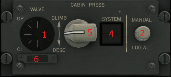
When slats are extended for T/O, cabin is pressurized to 100 ft below departure airport field elevation. Cabin will return to departure airport field elevation if aircraft descends before reaching 5,000 ft.
¶ 1. Outflow valve indicator
- Displays outflow valve position (in Auto or Manual mode)
¶ 2. MANUAL LDG ALT
- Used to enter landing field elevation if not available from FMS database.
- Inhibited with CABIN PRESS switch in MANUAL mode.
- Knob must be turned 120o to operate.
- Value is shown on Air Synoptic (boxed).
¶ 3. DITCHING Switch
Controls the rate of depressurization, and seals any ports associated with the Air System that would allow entry of water after ditching
ON (Pressed and illuminated)
- Maintains existing cabin altitude during descent
- At 2500 ft or <.5 PSID (whichever 1st)
- -Packs and bleeds shut off
- -GPWS is inhibited
- -Avionics venturi closes (in auto mode)
- -Outflow valve opens (in auto mode)
- -Ram Air Doors close
- At 1000 ft
- Outflow valve closes.
¶ 4. SYSTEM – SELECT / MANUAL Switch
Allows selection between MANUAL and AUTO
Two alternating auto channels (1 primary, 1 stby)
SELECT (illuminated)
- Both (auto) control channels failed. System has automatically switched to manual mode.
MANUAL (pressed and illuminated)
- System locked in Manual mode.
- Pressing a second time selects other auto channel.
¶ 5. CLIMB – DESC
Allows manual selection of outflow valve position in manual mode
¶ 6. CLOSED (illuminated)
Indicates that the outflow valve is fully closed
¶ Anti Ice
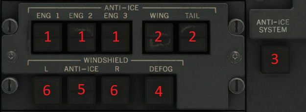
The Anti-Ice “System” refers to ENG, WING, TAIL and WINDSHIELD Anti-Ice. When anti-ice is required, these should all be ON. The primary method of ice detection is the Ice Detection System. If an ICE DETECTED alert is displayed, Anti-Ice must be turned on.
If the aircraft is equipped with an operational Automatic Anti-Ice system, anti-ice will automatically engage when required.
Icing Conditions Definition
Icing conditions exist on the ground when:
- OAT 6O or less (42O F), and 1 of the following:
- -Visible moisture
- -OAT / Dew point within 3OC (5O F) (gnd or Flt)
- -Snow, slush, ice or standing water on taxiways
Icing conditions exist in flight when:
- TAT 6O or less(42O F), and 1 of the following:
- -Visible moisture
- -OAT / Dew point within 3OC (5O F) (gnd or Flt)
- -ICE DETECTED alert displayed (non auto A/I)
- -Visible ice accumulates on the aircraft
Engine Run-up - GE
When anti-ice is used during ground operations in icing condit ions, perform an engine run -up of 60% N1 for 30 seconds prior to takeoff. This run -up should also be performed if anti-ice is used during ground operation for any period greater than 30 minutes, and repeated at intervals of no greater than 30 minutes.
Engine Run-up – P&W
When anti-ice is used during ground operations in icing conditions, perform a momentary engine run -up of (min) 50% N1 prior to takeoff. This run-up should also be performed at intervals of no greater than 15 minutes during ground operat ions with anti-ice on.
¶ 1. ENGINE ANTI-ICE Switch (1,2,3)
Switch Opens and closes respective engine anti-ice
shutoff valves.
ON
-Illuminates when anti ice is on.
DISAG
-Shutoff valve in transit, or remains illuminated if:
-Disagreement between switch and valve.
¶ 2. WING and TAIL ANTI-ICE Switches
Opens and closes the wing / tail anti-ice shutoff valves
Wing A/I uses Air Sys 1 & 3 – Tail uses Air Sys 2
ON
- The respective switch is on
DISAG
- On the Ground: Valve is open regardless of switch position
- In Flight: Valve is in transit, or disagreement between valve and switch position.
¶ 3. ANTI-ICE SYSTEM Manual Swich (Auto A/I Acft Only)
Pressing switch (MANUAL illum.) deselects the auto function, and allows pilot control of Eng, Wing and Tail Anti-Ice.
Manual
- System reverts from Auto to Manual due to a malfunction, or
- System is pilot-selected to Manual.
Note – Auto anti-ice is optional on MD-11s. If equipped with auto antiice, the system MUST be selected to MANUAL if the pilot wishes to override the auto function, and control anti-ice functions manually.
¶ 4. WINDSHIELD DEFOG Switch
Turns Low heat to inner windshield pane on or off
OFF (light extinguished)
- Defog is commanded on
Under normal conditions, Defog should always
be on in flight. Defog automatically turns on
when electric power is applied to the aircraft.
¶ 5. Windshield ANTI-ICE HIGH/NORM Switch
Provides High or Normal heat to the windshield.
Anti-Ice system defaults to NORM when powered.
HIGH
- Only used to deice windshield when NORM is insufficient
¶ 6. L / R WINDSHIELD ANTI-ICE Switch
Switch turns power to the windshield anti-ice controller on / off
ON
- Anti-Ice is on (NORM or HIGH)
Windshield Anti-Ice is not controlled by the automatic anti-ice system (if applicable), and must be manually turned on when icing conditions are anticipated or encountered.
¶ Forward Overhead

¶ 1. WINDSHLD WIPE Selector - (Captain and First Officer)
Each wiper has an OFF, SLOW, FAST speed. When selected OFF, the wiper and arm assembly move to the vertical parked position.
Operation on a dry surface is not recommended.
¶ 2. FUEL DUMP EMER STOP Switch - amber
Alternate action switch that electrically overrides the fuel DUMP switch by reversing the signal and stopping the fuel dump sequence. Illuminates amber if dump valves have been commanded closed.
The fuel dump sequence can be restarted by pushing the FUEL DUMP
EMER STOP switch a second time.
¶ 3. DOME Switch
Turns dome lights on and off.
¶ 4. OVHD PNL FLOOD Rheostats
Outer rheostat regulates intensity of overhead panel switchplate lighting.
Inner rheostat regulates intensity of overhead panel floodlights.
All lights are off when rheostats are turned completely counterclockwise.
Light intensity increases by turning rheostat in a clockwise direction.
¶ 5. INSTR & PED PNL FLOOD Rheostats
Outer rheostat regulates intensity of instrument panel and pedestal switchplate lighting.
Inner rheostat regulates intensity of instrument panel and pedestal floodlights.
All associated lighting is off when rheostats are turned completely counterclockwise.
¶ 6. EMER LT Switch
OFF
- Normal for ground operations. Emergency lights will not illuminate. Batteries will charge when power is available. EMER LTS DISARM alert will be displayed on EAD.
ARM
- Normal for flight. Allows emergency lights to illuminate automatically if normal electrical power is interrupted. Connects batteries to charging system if power is available.
ON
- For ground test. Illuminates emergency lights as long as power is available. EMER LTS DISARM alert is displayed on EAD.
¶ 7. STBY COMP Switch - blue
Turns on the standby compass light. ON illuminates blue.
¶ 8. EMER LT TEST Button
When this button is pushed:
- Emergency lights illuminate.
- Integral batteries are tested under load.
- EMER LTS TEST PASS alert is displayed on EAD when all circuits and batteries are satisfactory.
If EMER LTS TST PASS does not appear, batteries with abnormal voltage can be identified on the SD STATUS page MAINT column by pushing the button again.
¶ 9. LDG LT Switch (L and R)
Activates respective primary landing lights mounted on the forward fuselage.
RET
- Lamp are off and the lights are retracted flush with the fuselage.
EXT OFF
- Lights are extended but the lamps are off.
EXT ON
- Lights are extended and the lamps are on.
¶ 10. NOSE LT Switch
Turns on nose gear landing lights for taxiing and landing. These lights will
only come on if landing gear control handle is in DOWN position.
OFF
- Lights are off.
TAXI
- Lights are on with less than full intensity for ground operation.
LAND
- Lights are on at full intensity for landing.
¶ 11. NO SMOKE Sign Switch
ON
- Illuminates NO SMOKING signs and sounds a chime in cabin.
AUTO or OFF
- NO SMOKING signs will illuminate and a chime will sound in cabin if a cabin decompression occurs (cabin altitude exceeds 10,000 feet).
AUTO
- NO SMOKING - sign will illuminate and a chime will sound in cabin when landing gear handle is in DOWN position.
¶ 12. SEAT BELTS Sign Switch
ON
- Illuminates FASTEN SEAT BELT and RETURN TO CABIN signs and sounds a chime in cabin.
AUTO or OFF
- FASTEN SEAT BELT signs will illuminate and a chime will sound in cabin if a cabin decompression occurs (cabin altitude exceeds 10,000 feet). RETURN TO CABIN signs will not illuminate.
AUTO
- FASTEN SEAT BELT and RETURN TO CABIN signs will illuminate and a chime will sound in cabin when FLAP handle is out of the UP position and/or landing GEAR handle is in DOWN position.
¶ 13. LDG LT Switch (L)
Activates respective primary landing lights mounted on the forward fuselage.
RET
- Lamp are off and the lights are retracted flush with the fuselage.
EXT OFF
- Lights are extended but the lamps are off.
EXT ON
- Lights are extended and the lamps are on.
¶ 14. LDG LT Switch (R)
Activates respective primary landing lights mounted on the forward fuselage.
RET
- Lamp are off and the lights are retracted flush with the fuselage.
EXT OFF
- Lights are extended but the lamps are off.
EXT ON
- Lights are extended and the lamps are on.
¶ 15. NAV Switch - amber
Turns on position lights in each wing tip. The two left forward lights emit red lighting. The two right forward lights emit green lighting. The two aft lights in each wing tip emit white lighting.
OFF
- illuminates amber when lights are off.
¶ 16. LOGO Switch - blue
Turns on logo light on horizontal stabilizer to illuminate vertical stabilizer.
ON
- illuminates blue when switch is selected on.
OFF
- illuminates blue when switch is selected off.
¶ 17. BCN Switch - amber
Turns on beacon lights on top and bottom of aircraft.
OFF
- illuminates amber when anti-collision lights are off.
¶ 18. HI-INT Switch - blue
Turns on supplemental high intensity recognition lights on each wing tip. Each wing tip has three lights (two forward and one aft). Lights flash in sequence with anticollision lights. Illuminates blue when high intensity lights are off.
¶ 19. CALL RESET Button
Pushing the button will turn off the blue CALL light.
¶ Pedestal
¶ Auto brake System

¶ 1. AUTO BRAKE Selector
OFF
- ABS is not armed but manual braking is available.
T.O.
- Provides maximum braking from brake system 1 and 2 when spoilers deploy during RTO with ABS armed above 100 knots. Below 100 knots, MIN braking is provided.
MIN, MED, MAX
- Selected braking level engages when spoilers are deployed automatically or manually during landing with ABS armed.
If any AFS land mode is selected with aircraft on ground, the ABS disarms
and the ABS DISARM light illuminates.
¶ 2. ANTI-SKID OFF Switch
Push to select anti-skid off. Illuminates amber when anti-skid is selected off.
¶ 3. AUX HYD PUMP 1 Switch - blue
Turns on electric aux pump 1 to pressurize hydraulic system 3 if pressure is lost. Hydraulic system 3 powers brake system 2. Pump can also be turned on from the HYD control panel.
¶ 4. BRAKE SYS HYD PRESS Gage (1 and 2)
Pointer 1 shows hydraulic pressure in brake system 1. Pressure shown is highest of hydraulic system 1 or brake system 1 accumulator.
Pointer 2 shows hydraulic pressure in brake system 2. Pressure shown is highest of hydraulic system 3 or brake system 2 accumulator.
¶ SLAT STOW Switch - amber

SLAT STOW
- With the FLAP/SLAT handle in retract position, pushing the SLAT STOW switch deactivates the slat extend function. Switch illuminates amber. With the FLAP/SLAT handle positioned greater than 3°, NO SLATS is displayed on the PFD.
The SLAT STOW alert is displayed on the SD CONFIGURATION page. A SLAT DISAG alert is displayed when operating the SLAT STOW switch with slats extended.
Pushing the SLAT STOW switch with slats stowed and flaps extended extends the slats.
¶ Communication
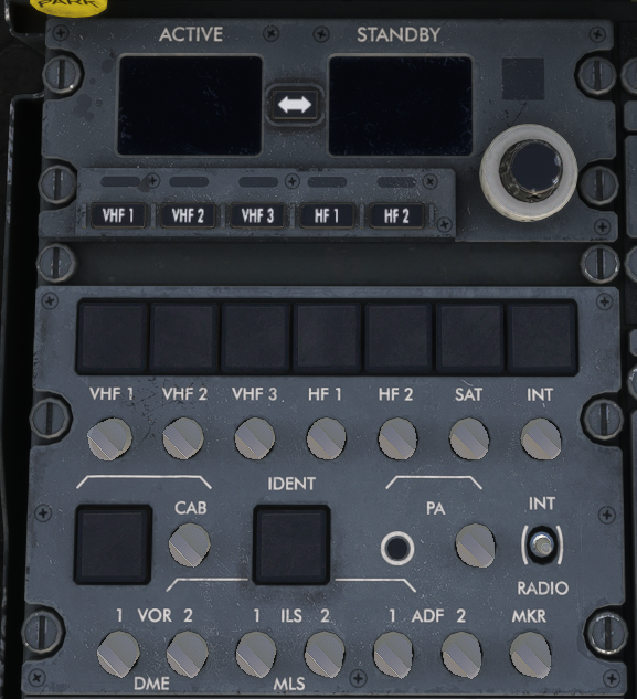
¶ 1. Radio control panel
Pressing radio select button displays active and standby frequencies currently tuned for respective radio, and allows the pilot to change frequencies on that radio using the tuning knobs
¶ 2. Comm Sys Select buttons
Communication system select buttons are used to select the communication system from which transmissions will be made
¶ 3. Service Interphone Select button
¶ 4. Flight Interphone Select button
¶ 5. Volume control knobs
Volume controls for respective Communication system
¶ Throttle Quadrant
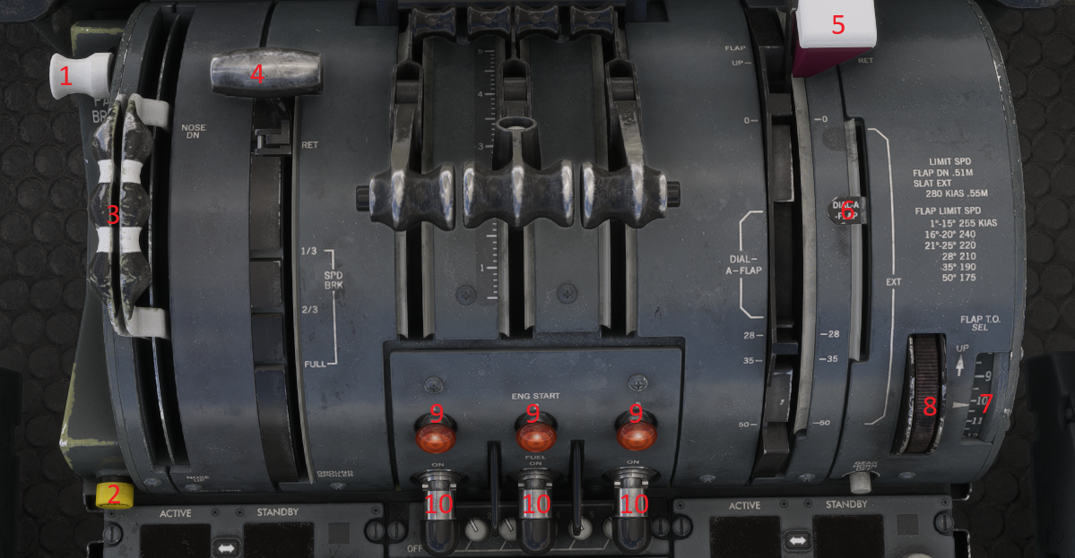
¶ 1. PARK BRAKE Handle
Brakes are fully applied for parking by positioning the handle aft. Pressure from brake system 1 and 2 is maintained with trapped fluid.
¶ 2. PARK Light - amber
Illuminates amber when PARK BRAKE handle is set to park position. Will extinguish when parking brake is released.
¶ 3. LONG TRIM Handles
The handles provide direct mechanical control of the horizontal stabilizer control valves. The trim handles have the same function as the electric control wheel trim switches, except that they have override authority over LSAS or autopilot inputs except in DUAL or SINGLE LAND mode.
Moving the handles together provides control of the horizontal stabilizer. Stabilizer movement rate is determined by airspeed and altitude. Both handles must be operated together to move the horizontal stabilizer.
¶ 4. SPOILER Handle
The spoiler handle is used to either select automatic operating modes or to control the manual modes of the spoiler system.
When arming for automatic spoiler operation, the spoiler handle, which is spring-loaded to RET, must be at RET before it can be pulled up to armed. When armed (up), a red placard labeled ARM in white letters, is visible on
both sides of the handle.
When auto spoilers are armed, automatic operation is as follows:
- During a rejected takeoff, ground spoilers automatically extend when groundspeed is less than 80 knots, and any two of the three throttles move into reverse thrust. With groundspeed greater than 80 knots, moving any two throttles to idle deploys ground spoilers.
- During landing, with flaps 30° or greater and after main wheel spinup, the spoiler handle moves to approximately the two-thirds position. At nose gear touchdown, the handle moves to full ground spoiler position and the ground spoilers fully extend.
- After ground spoiler extension, advancing throttle 2 automatically moves the SPOILER handle to full forward, retracting the spoilers. If the number 2 engine throttle is not at idle at main gear spin-up it is possible that the AGS will initiate deployment and will then immediately retract the spoilers. If this occurs, ground spoilers must be manually extended.
Manual spoiler operation is as follows:
- In flight, the handle controls the speed brake mode when the "T" handle release is squeezed and pulled aft to the 1/3, 2/3, or FULL position. The handle stops at FULL.
1/3 - all 5 spoilers on both wings extend 10°.
2/3
- all 5 spoilers on both wings extend 20°.
FULL
- all 5 spoilers on both wings extend 30°.
- On the ground, the handle controls the ground spoiler mode when pulled up and aft to the GROUND SPOILER position. Pulling the handle up again locks it aft.
- The handle will not move to the GROUND SPOILER position until the nose gear strut is compressed during landing.
¶ 5. FLAP/SLAT Handle
Lifting FLAP/SLAT handle up and pulling aft to latch in preselected takeoff DIAL-A-FLAP detent, 28° go-around gate, or 35°/50° landing flap detent, extends the flaps and the slats.
Rotating the FLAP T.O. SEL thumbwheel until the proper takeoff flap setting appears in the FLAP T.O. SEL indicator sets the takeoff DIAL-A-FLAP detent.
The 28° go-around detent has a gate/stop to prevent inadvertent extension/retraction of the flaps. The handle can be maneuvered past the gate/stop.
Lifting the handle up and aft past the go-around gate to either the 35° or the 50° landing detent extends landing flaps.
Lifting the handle out of the detent and moving it forward past the go-around gate retracts landing flaps.
Positioning the handle at the 0°/EXT detent (flaps retracted/slats extended) retracts the flaps without retracting the slats. Maneuvering the handle from the 0°/EXT detent gate to positively engage it in the FLAP UP/SLAT RET detent retracts the slats.
To prevent unintentional slat extension:
When retracting slats, be sure FLAP/SLAT handle is firmly engaged in the FLAP UP/SLAT RET detent.
After flap/slat retraction, do not push, pull, or otherwise manipulate the FLAP/SLAT handle unless extension is desired.
¶ 6. DIAL-A-FLAP Detent Indicator
Indicates position of DIAL-A-FLAP detent. The detent position varies with the DIAL-A-FLAP setting.
¶ 7. FLAP T.O. SEL Indicator
Indicates the preselected DIAL-A-FLAP takeoff flap setting.
¶ 8. FLAP T.O. SEL Thumbwheel
When rotated, sets the DIAL-A-FLAP takeoff flap setting for any flap setting
between 10° and 25°.
¶ 9. ENG START Switch (3) - amber
Pulling this switch will:
- Energize a coil that holds the switch out.
- Energize the engine starter valve open.
- Illuminate the switch amber.
- Supply power to the FADEC computer.
At about 45-52 percent the ENG START switch will pop in and the light will extinguish indicating that the starter air valve has closed. The MSC controls the start sequence. This switch cannot illuminate until the appropriate electrical bus is powered.
¶ 10. FUEL Switch (3) - red
This switch supplies electrical power to a fuel metering device. The fuel metering device then operates the fuel shutoff valve. This switch illuminates red during engine fire and ENG/APU FIRE test. Moving the switch to the ON initiates ignition and fuel if the ENG START switch is out and the ENG IGN switch is selected A or B. The FSC automatically turns on the fuel pumps in tanks 1, 2, or 3 when the respective ENG START switch or FUEL switch is moved to ON.
¶ Transponder
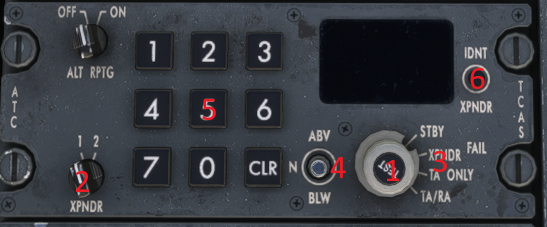
¶ 1. TEST Button
Push
- Activates system test.
¶ 2. XPNDR Selector
1/2
- Selects transponder 1 or 2.
¶ 3. Mode Selector
STBY
- Applies power to the transponder but inhibits response to ground interrogation.
XPNDR
- Allows response to ground interrogation.
TA ONLY
- Selects TCAS Traffic Advisory mode only.
TA/RA
- Selects Traffic/Resolution Advisory mode.
ALT RPTG OFF
- Turns altitude reporting off.
Alt reporting is off by default in the cold and dark state. Alt reporting needs to be turned on to squawk mode C on vatsim.
¶ 4. ABV/BLW Selector
ABV
- Selects display of traffic that is above (up to 9,900 feet) and below down to 2,700 feet.
N
- Selects display of traffic within +/- 2,700 feet of own altitude.
BLW
- Selects display of traffic that is below (down to 9,900 feet) and above up to 2,700 feet.
¶ 5. Keys
Allows code selection. CLR key clears the selection.
¶ 6. Ident Button
Allows to trigger ATC IDENT